Do you have a question about the Conquest Imaging GE Voluson E10 and is the answer not in the manual?
Lists other ultrasound training courses offered by Conquest Imaging.
Describes the flow of signals from probes to display, including FEP and BEP.
Details parts of the ultrasound system that handle analog signal processing.
Lists the boards comprising the front end beamforming electronics.
Recognizes probe types and switches between probe connectors.
Supports Tx/Rx for 128 channels.
Extends channels to 192 or 256.
Receives data from FEP, stores it, performs scan conversion, and drives monitors.
Handles system control, image processing, and peripheral control.
Main storage device, divided into partitions (System, User, Rescue, Linux).
Supplies DVI Video to RTV board, offers contrast enhancement.
Distributes DVI-D info and converts DVI-D to S-Video.
Panel at the rear with VGA, USB, Network, and S-Video connectors.
Allows ECG inputs for synchronization with patient studies.
Includes display, touch screen, and console modules.
Main user interface for input, communication, and display.
Details how the control console can be rotated, translated, and adjusted.
Displays ultrasound images on a 23" color LCD.
Audio is provided by two 8 Ohm speakers.
Steps to connect power and turn on the system.
Intended to reduce boot-up time by saving memory content.
Steps to safely shut down the system.
Discusses air filters and cooling system.
A 2D image of echo signal amplitude used for measurement and orientation.
Minimizes acoustic aberrations and enhances resolution using tissue harmonics.
Scrolling display of soft tissue structure over time, used for cardiac measurements.
Detects motion as a 2D display, shows blood flow velocity and direction.
Uses signal amplitude to detect movement, independent of velocity and angle.
Spectral Doppler mode showing flow velocity vs. time, indicating turbulent or laminar flow.
Optional mode using two crystals to detect high velocities without aliasing.
Covers 4D imaging for reconstructing 3D images from sequential 2D images.
Standard for file structure and communications for medical images.
Information needed from system administrator for network setup.
Refers to communication between ultrasound systems and other providers as dataflows.
Describes how to set up TCP/IP Configuration for the Voluson E-Series.
Describes WLAN connectivity and setup procedures.
Allows configuration of DICOM, Archive, and Network settings.
Dialog section for setting up details of DICOM target nodes (image servers).
Details for AE Title, Station Name, Retry Count, etc.
Importance of backing up system configuration and patient archive.
How to access and perform backup/restore operations.
Details what Image/Scan Settings are included in a small backup.
Steps to load previously saved backups.
Details the data included in a full system configuration backup.
Guidelines for connecting and using USB storage devices.
Procedures for safely disconnecting USB devices.
Window showing connected USB and Network drives.
Instructions for cleaning air filters to ensure system performance.
Instructions for cleaning the optical trackball.
Recommendation for testing and replacing the motherboard battery.
Warnings and precautions regarding electrical safety.
Discusses EMI and measures to reduce interference.
Explains ESD and precautions to prevent damage.
General fire safety practices for electrical equipment.
General cautions for handling batteries and system components.
Describes the normal power on and boot sequence.
Preliminary checks before connecting AC power.
Steps to switch on the system after connecting AC power.
Intended to reduce boot-up time by saving memory content.
How to collect vital system information before troubleshooting.
Troubleshooting tree for when the system doesn't start to boot.
Suggestions for troubleshooting monitor malfunctions, including settings and tests.
Covers common operator panel issues like no audio or no video.
Troubleshooting steps for a non-responsive touch panel.
Troubleshooting steps for probe recognition issues.
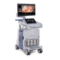
Shows the basic layout of the Voluson E10 system components.
System must be completely powered down before parts replacement.
Details the order of panel removal for system access.
Instructions on how to unlock and remove the footrest.
Steps for removing the front panel from the console.
Shows the locations of screws for front panel removal.
Instructions for removing the side panel.
Instructions for removing the back panel after the side panel.
Lists various boards and modules within the system.
Information related to the power supply component.
Information related to the front end components.
Information related to the back end components.
Instructions for replacing the monitor and arm.
Details ergonomic adjustments for the control console.
Instructions on how to rotate the console.
Instructions on how to adjust the console height.
Details on the adjustability of the video monitor.
A checklist of parameters for network configuration.
Information required for configuring print devices.
Information required for HIS/RIS server configuration.
Lists DICOM devices that can be connected to the system.
Additional information for network configuration.
| Brand | Conquest Imaging |
|---|---|
| Model | GE Voluson E10 |
| Category | Medical Equipment |
| Language | English |