6 Commander SE Advanced User Guide
Issue Number: 4
Multi-drop Converters
• Amplicon Magic 485F25 or Magic 485F9
(485F25 refers to 25 way D-type connector and 485F9 refers to 9 way D-type connector)
www.amplicon.co.uk
E-mail: support@amplicon.co.uk
• Westermo MA44
www.westermo.dircon.co.uk
E-mail: sales@westermo.co.uk
When using either of the above converters, or any other suitable converter with Commander SE, it is recommended that no
terminating resistors be connected on the network. This applies to any of the drives on the network and also any converter
used. It may be necessary to 'link out' the terminating resistor within the converter depending on which type is used. The
information on how to link out the terminating resistor will normally be contained in the user information supplied with the
converter. Terminating resistors are of little or no value when used on EIA485 networks operating at or below 19.2kBaud.
The Amplicon Magic 485F25 or F9 are non-isolated and the Westermo MA44 is isolated.
Isolation of the communications port
The communications port of the Commander SE drive is double-insulated from the power electronics and
single-insulated from the status relay contacts. Providing that the voltage on the status relay contacts
does not exceed 110V, the communications port meets the requirements for SELV in EN50178. However in
the event of a serious fault in the drive, the safety barriers could be breached. Therefore when using the
communications port with a personal computer or centralised controller e.g PLC, an isolation device must
be included with rated voltage at least equal to the drive supply voltage. Ensure that the correct fuses are
installed at the drive input, and that the drive is connected to the correct supply voltage.
Isolation Devices
1. OP232/B1 Isolator
www.scimar.co.uk
E-mail: sales@scimar.co.uk
2. 232SPM14 Isolator - 4 channel
95POP2 Isolator - 2 channel
www.bb-elec.com
www.bb-europe.com
Fitting an RJ45 is a relatively simple process. The following instructions are provided to ensure a good reliable termination.
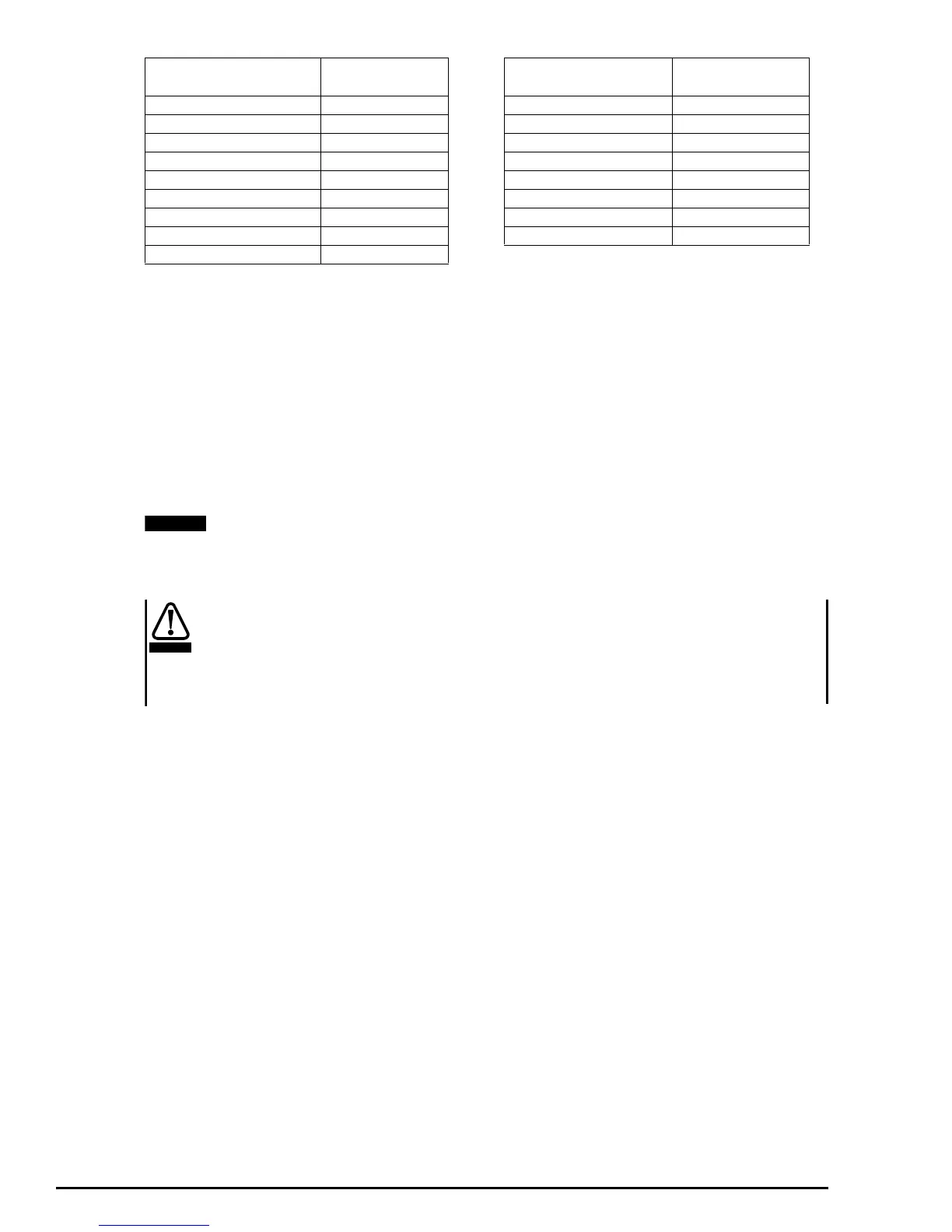
EIA232 9 Way
D-type connector
Pin Function
EIA485
RJ45 Connector
Pin Function
1 Not connected 1 Not connected
2TX 2RXTX
3RX 3 0V
4 DTR 4 +28V Input
5 GND 5 Not connected
6 Not connected 6 TXEN\
7 RTS 7 RXTX\
8 N/C 8 Not connected
9 Not connected
NOTE
WARNING