Commander SE Advanced User Guide 79
Issue Number: 4
This parameter is set if the output bridge is transferring power from the motor to the DC Bus.
This parameter is set when power is being dumped in the optional braking resistor if fitted.
This flag is set when the dynamic brake is active and the braking energy accumulator is greater than 75%.
This parameter is a 1 if the pre-ramp reference is negative (reverse), and is a 0 if pre-ramp reference is positive (forward).
This parameter is a 1 if the post-ramp reference is negative (reverse), and a 0 if post-ramp reference is positive (forward).
Indicates a loss of input supply to the drive.
This flag is set if the motor active current is larger than 105% of the programmed motor rated active current and the overload
accumulator is greater than 75% to warn that if the motor current is not reduced the drive will trip on an Ixt overload or will
reduce the current automatically depending on the protection mode programmed in parameter 4.16.
This flag is set if the IGBT junction temperature calculated from the drive thermal model is above 135°C, or if the heatsink
temperature has made the switching frequency decrease.
The following table indicates how the switching frequency is controlled.
*Commander SE Size 4 >100°C
The switching frequency and drive thermal model are updated once per second. Whenever the drive has reduced the
switching frequency, this alarm is set. Also, when this alarm has been set, the drive’s display will flash ‘hot’.
Also see parameters 5.18 and 7.04.
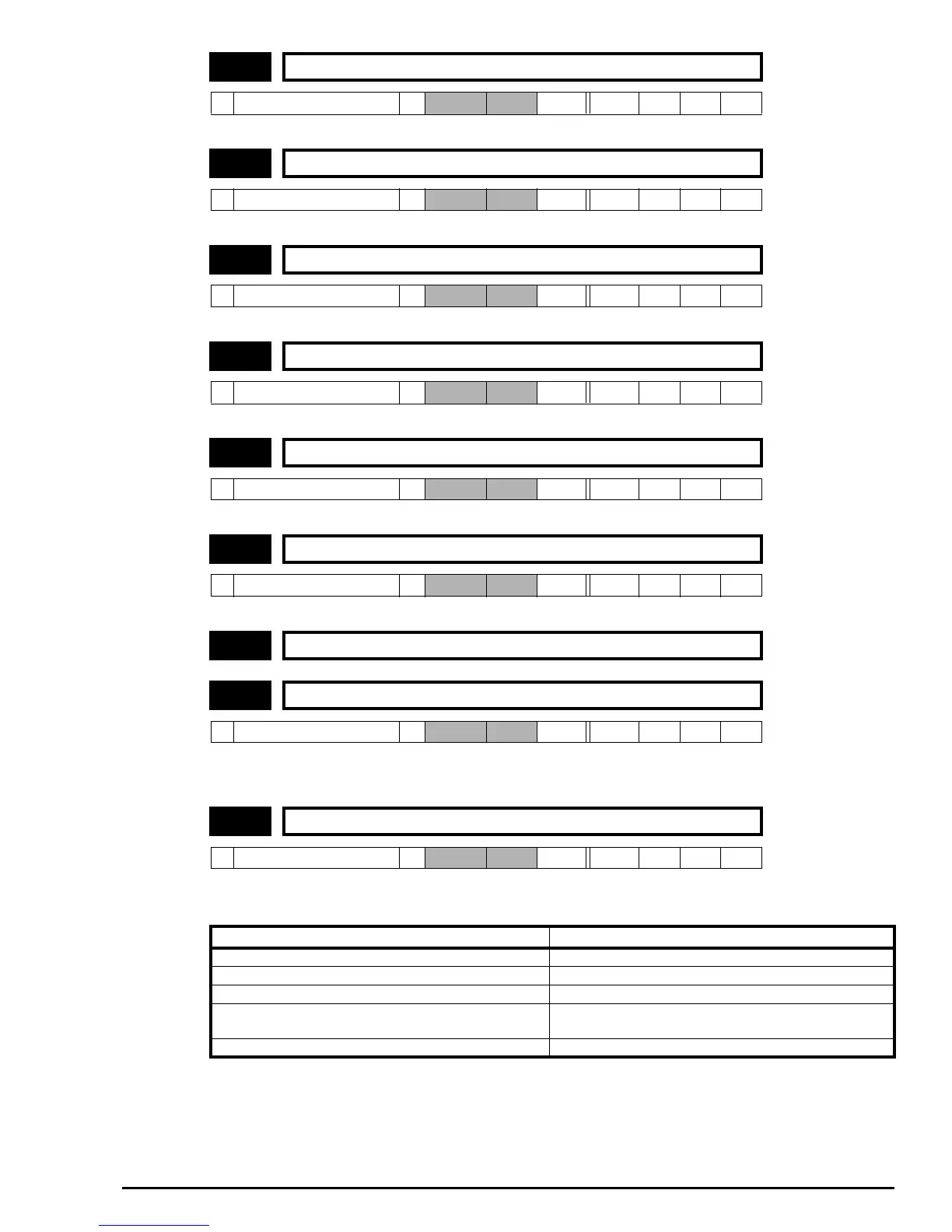
10.10 Motor regenerating indicator
Ú
0 or 1
Ö
RO Bit P
10.11 Dynamic brake active indicator
Ú
0 or 1
Ö
RO Bit P
10.12 Dynamic brake alarm indicator
Ú
0 or 1
Ö
RO Bit P
10.13 Direction demanded indicator
Ú
0 or 1
Ö
RO Bit P
10.14 Direction running indicator
Ú
0 or 1
Ö
RO Bit P
10.15 AC supply loss indicator
Ú
0 or 1
Ö
RO Bit P
10.16 Unused parameter
10.17 Motor current overload indicator
Ú
0 or 1
Ö
RO Bit P
10.18 Drive temperature alarm indicator
Ú
0 or 1
Ö
RO Bit P
Drive condition Action
Heatsink >95°C* Trip drive
Heatsink >92°C Reduce switching frequency to 3kHz
Heatsink >88°C Reduce switching frequency to 6kHz
Heatsink <85°C and IGBT temperature at new switching
frequency <135°C
Allow an increase in the switching frequency
IGBT temperature >135°C Reduce switching frequency. If it is 3kHz minimum, trip drive