3-13
1010PVNFM-3A
Section 3
1. Perform all the required menu steps up until the point where the flow computer issues the
number index and prompts you to press <ENT> to finish the transducer install routine.
Make a note of the number index displayed in the Pick/Install menu. Check to ensure that
you have a matched set of transducers. They both should have the same S/N number but
marked with either an “A” or “B” (e.g., 100A and 100B).
2. Temporarily position one of the frames on the pipe where you will be mounting it. Ensure
that this is a smooth area without any raised areas (seams, etc.) With a pencil or chalk,
mark a generous area around the frame (1/2” on either side and half again the length front
and back). Remove the assembly.
3. Prepare the area you marked by de-greasing surface, if needed, and removing any grit,
corrosion, rust, loose paint or surface irregularities with the abrasive material provided.
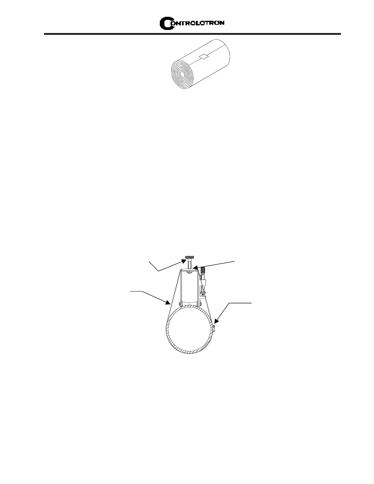
4. Put a mounting strap around the pipe and engage an end into adjusting screw (screw should
be pointing up). Position frame in the middle of area you have cleaned and centered on the
pipe with its angled end facing away from where the other frame will sit.
WRAPPING STRAP UNDER PIPE AND ATTACHING TO ADJUSTING SCREW
5. Slide the mounting strap over it (and under the clip if there is one) and tighten with a
screwdriver. While tightening, check to ensure that the center of the tapered roller is
centered on the pipe.
6. Attach the second frame to the spacer bar with an index spacer screw into the index hole
specified in Step 1. The angle on the frame should be facing away from the direction the
length of the bar is going. Now attach the free end of the spacer bar by inserting an index
spacer screw through the REF hole on the spacer bar and then into the hole on the mounted
frame. Tighten. Sight to ensure that this frame is lined up in center of pipe and while
holding alignment, place a dot (with pencil or chalk) in the center of the tapered roller
Mounting Strap
Adjusting Screw
Transducer Clamping
Screw
Mounting Strap
Spring Clip
MYLAR™ SPACING GUIDE