3-15
1010PVNFM-3A
Section 3
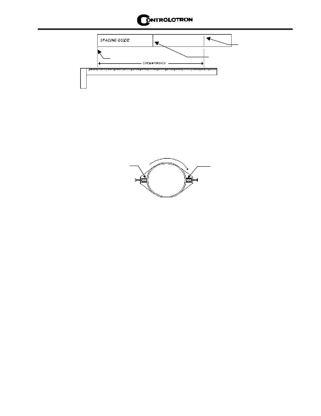
Overlap Edge
Mark (or fold) exactly
at half-way point
Ltn mark
11. Reinstall the spacing guide; its left edge abutting the transducers edge mark on the pipe
and the overlapping edge in line with the dot (now a line) on the pipe (see “C” on previous
page). Tape it in this position on the pipe. Take the second frame and place it against the
edge of the guide with its tapered roller centered on the center mark on the guide. Tempo-
rarily position the frame (in the 3 o’clock position opposite the mounted frame - see below)
where it will be mounted. Ensure that this is a smooth area without any raised spots
(seams, etc.). Mark a generous area around the mounting frames (1/2-inch on either side
and half again the length front and back) with a pencil or chalk. Remove the frame and the
mylar guide.
FINDING THE HALFWAY DISTANCE
ALIGNING THE TRANSDUCERS FOR DIRECT MODE OPERATION
12. Prepare the area you marked by de-greasing the surface, if needed, and removing any grit,
corrosion, rust, loose paint or surface irregularities with the abrasive pipe conditioning
material provided. Clean the pipe of any debris and abrasive particles.
13. Replace the mylar guide back in the same position it was in and retape it to the pipe.
14. Put a mounting strap around the pipe and engage an end into adjusting screw (screw
should be pointing up). Position frame in the middle of area you have cleaned and cen-
tered on the pipe with its angled end facing away from where the other frame will sit; and
aligned with the edge and center marks on the guide. Slide the mounting strap over it (and
under the clip if there is one) and tighten with a screwdriver. While tightening, check to
ensure that the center of the tapered roller is centered on the pipe.
15. Apply a 1/8-inch continuous bead of couplant compound down the center (the long way) of
the contact surface of one of the transducers. Place the transducer into one of the frames
so that the couplant compound does not smear until it contacts the pipe. Slide it in until it
butts against the stop and, while holding in-place, tighten the transducer clamping screw
tight enough to hold firmly in-place. Do the same with the other transducer.
16. Connect the transducer cable, ensuring that you have observed the upstream/downstream
orientation in respect to the cable and the input jack on the flow computer. If this is a dual-
channel unit, make sure you are connecting the cables to the correct channel’s input jacks.
Repeat this procedure for the number index transducer.
3 o’clock
Transducer
9 o’clock
Transducer