Fault
relay
output
Electronic
expansion
valve outputs
Mains
power
input
230V AC
Fan relay outputs
(double pole)
Compressor
contactor
output
Reverse
cycle valve
output
Solid state
relay output 1
24V AC to 230V AC
Solid state
relay output 2
AUX
relay
output
Indoor fan
control inputs
Temperzone
© 6-2014
(24V AC or 12V DC)
Comp and
heat inputs
HP
switch
input
LP switch
or overload
input
0-10V inputs
indoor
fan
capacity
Earth
terminal
RS485 port 2
Modbus RTU
to slaves
0-10V output 1
outdoor fan
0-10V output 2
outdoor fan
DRED
inputs
(dry contact)
Remote on/off
input
(dry contact)
Temperature
sensor inputs
Pressure
transducer
inputs
EXV1 EXV2 AUX
HI ME LO C1 CP HT C2
IN
#1
IN
#2
FLT
EARTH
High
HIGH
230
VAC
L N
1
CMC R/V
SSR
#1
SSR
#1
SSR
#2
SSR
#2
MED LOW
C3
C4
Power
Medium Low Comp Heat
HPT
LPT
J1
B
12
B2
A2
OV
V1
OV
V2
OV
D1
D2
D3
SC
ON
OV
A
5 VF OV 12 VC OV
J2
DL
AMB
OC
SL
DEI
IC
PROG JTAG
11 13
2 3 4 5 6 7 8 9 10 12 14 15 16
46
Shielded, 2 core, twisted
pair, control cable
(not supplied)
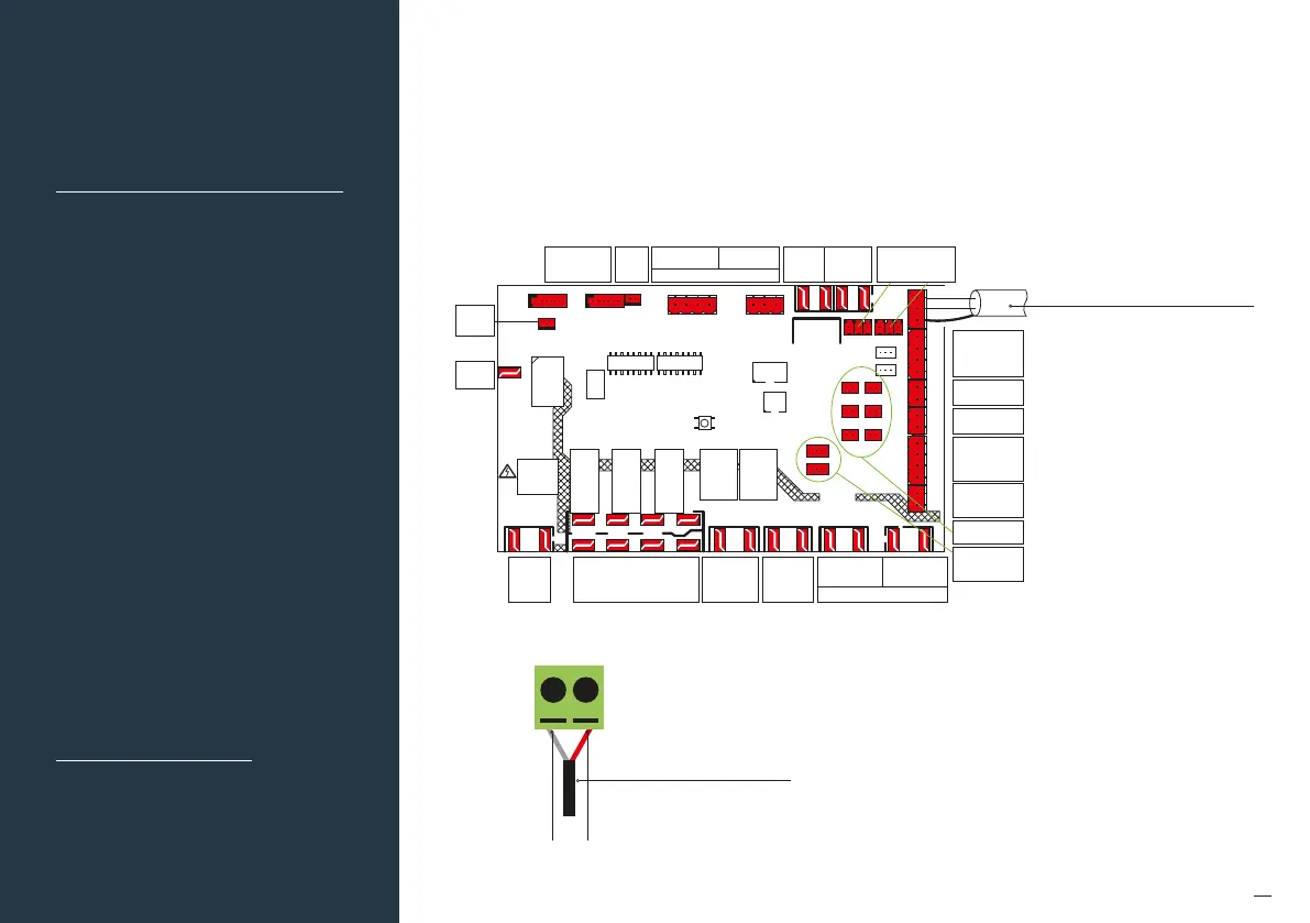
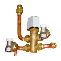
Fig (a) – Temperzone UC8 outdoor board
Connection
1. Connect a shielded, 2 core, twisted pair control cable from the C225 to the UC8 board in the condensing unit.
(This cable is supplied by the installer) .Polarity is critical see Fig (a) and (g) for correct connection.
2. Ensure the dip switches in the condensing unit are set correctly for the installed compressor type (digital
ixed speed) and fan speed control. Refer to the Temperzone service manual.
58. Unit make:
59. Temperzone
60. Unit must be tted with
UC8 Outdoor Board
Myzone Wiring
Connections to
Temperzone Units
Fig (g) – Myzone C225/C325TZ
Correct polarity
Shielded, 2 core, twisted
pair, control cable
(not supplied)
B
A