E
0
0.0[ ]
F
B
0 0.0[ ]
C
D
A
0 0.0[ ]
176FA281.11
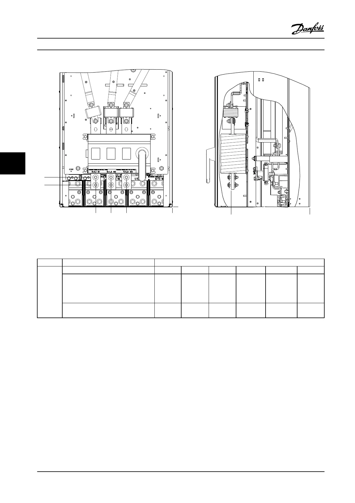
Figure 6.66 IP00 Enclosure Power Connections, Position of Disconnect Switch
Frame size Unit type Dimension for disconnect terminal, mm (in)
E2
IP00/CHASSIS A B C D E F
350/450 hp [250/315 kW] (400 V) and
475/600–650/850 hp
[355/450–500/630 KW]
(690 V)
381 (15.0) 245 (9.6) 334 (13.1) 423 (16.7) 256 (10.1) N/A
450/475–550/600 hp [315/355-400/450 kW]
(400 V)
383 (15.1) 244 (9.6) 334 (13.1) 424 (16.7) 109 (4.3) 149 (5.8)
Table 6.34 Disconnect Terminal Locations - Frame Size E2
Mechanical Installation Design Guide
152 Danfoss A/S © Rev. 2014-02-10 All rights reserved. MG34S222
66

 Loading...


