10.12 How to Access Parameters
10.12.1 Parameter Handling
The PNU (Parameter Number) is translated from the
register address contained in the Modbus read or write
message. The parameter number is translated to Modbus
as (10xparameter number) DECIMAL.
10.12.2 Storage of Data
The Coil 65 decimal determines whether data written to
the adjustable frequency drive is stored in EEPROM and
RAM (coil 65=1) or only in RAM (coil 65=0).
10.12.3
IND
The array index is set in holding register 9 and used when
accessing array parameters.
10.12.4
Text Blocks
Parameters stored as text strings are accessed in the same
way as the other parameters. The maximum text block size
is 20 characters. If a read request for a parameter is for
more characters than the parameter stores, the response is
truncated. If the read request for a parameter is for fewer
characters than the parameter stores, the response is
padded with spaces.
10.12.5
Conversion Factor
Since a parameter value can only be transferred as a whole
number, a conversion factor must be used to transfer
decimals. See chapter 10.8 Examples.
10.12.6
Parameter Values
Standard data types
Standard data types are int16, int32, uint8, uint16, and
uint32. They are stored as 4x registers (40001–4FFFF). The
parameters are read using function 03 HEX "Read Holding
Registers." Parameters are written using the function 6 HEX
"Preset Single Register" for 1 register (16-bits), and the
function 10 HEX "Preset Multiple Registers" for two
registers (32-bits). Readable sizes range from one register
(16 bits) up to ten registers (20 characters).
Non-standard data types
Non-standard data types are text strings and are stored as
4x registers (40001–4FFFF). The parameters are read using
function 03 HEX "Read Holding Registers" and written
using function 10 HEX "Preset Multiple Registers." Readable
sizes range from one register (two characters) up to ten
registers (20 characters).
10.13 FC Control Profile
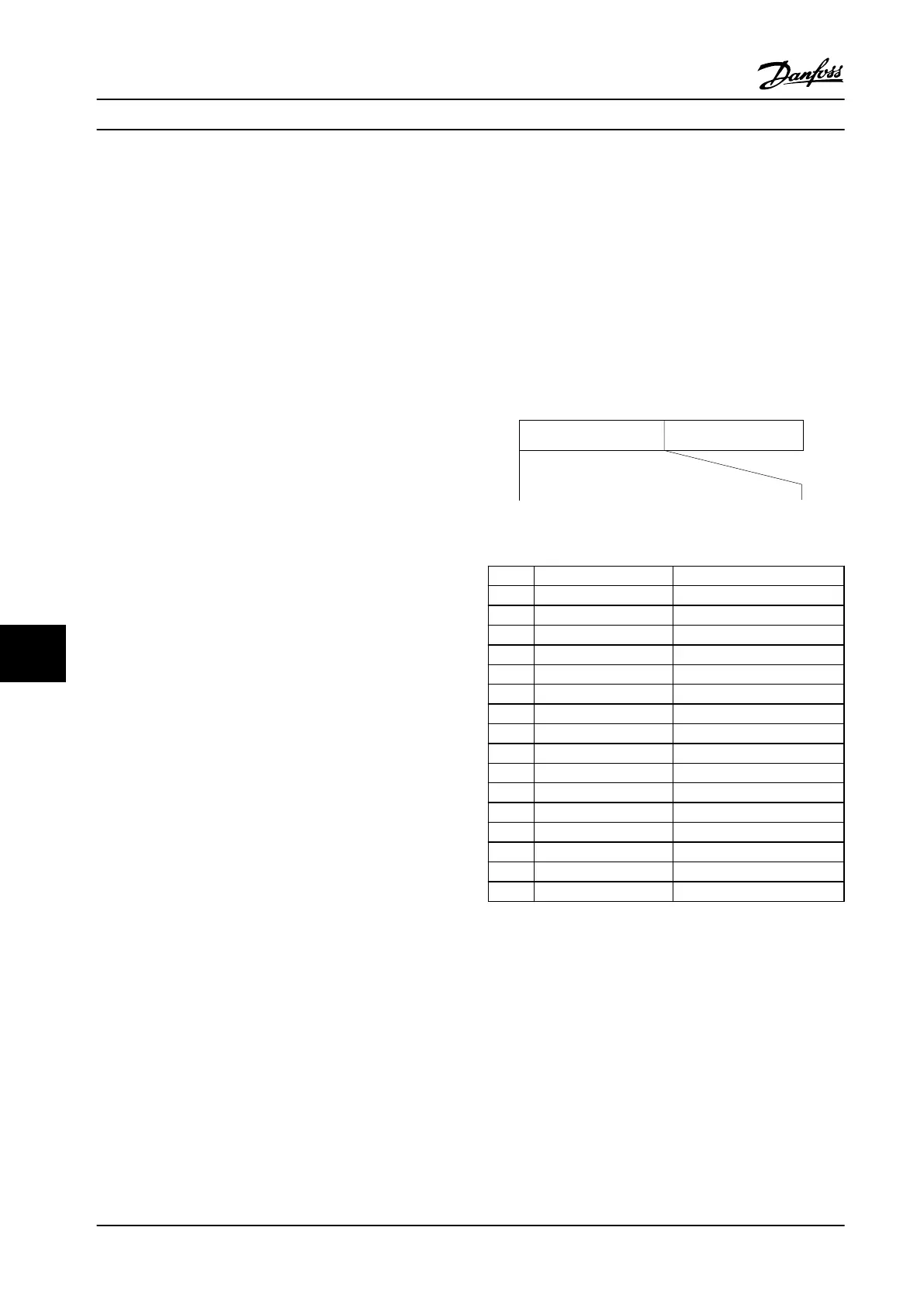
10.13.1 Control Word According to FC
Profile
Speed ref.CTW
Master-follower
130BA274.11
15 14 13 12 11 10 9 8 7 6 5 4 3 2 1 0
Bit
no.:
Figure 10.15 CW Master to Follower
Bit Bit value=0 Bit value=1
00 Reference value external selection lsb
01 Reference value external selection msb
02 DC brake Ramp
03 Coasting No coasting
04 Quick stop Ramp
05 Hold output frequency use ramp
06 Ramp stop Start
07 No function Reset
08 No function Jog
09 Ramp 1 Ramp 2
10 Data invalid Data valid
11 No function Relay 01 active
12 No function Relay 02 active
13 Parameter set-up selection lsb
14 Parameter set-up selection msb
15 No function Reverse
Explanation of the control bits
RS-485 Installation and Set... Design Guide
280 Danfoss A/S © Rev. 2014-02-10 All rights reserved. MG34S222
1010

 Loading...


