9.8 MCB 113 Extended Relay Card
The MCB 113 adds seven digital inputs, two analog
outputs, and four SPDT relays to the standard I/O of the
adjustable frequency drive, providing increased flexibility
and compliance with the German NAMUR NE37
recommendations.
The MCB 113 is a standard C1-option for the Danfoss VLT
®
AutomationDrive and is detected automatically after
mounting.
For information on mounting and installing the option, see
chapter 9.1.3 Slot C.
130BA965.10
121110987654321
4321 12111098765432121 13 14
+
-
+
-
+
-
+
-
+
-
+
-
+
-
+
-
+
-
+
-
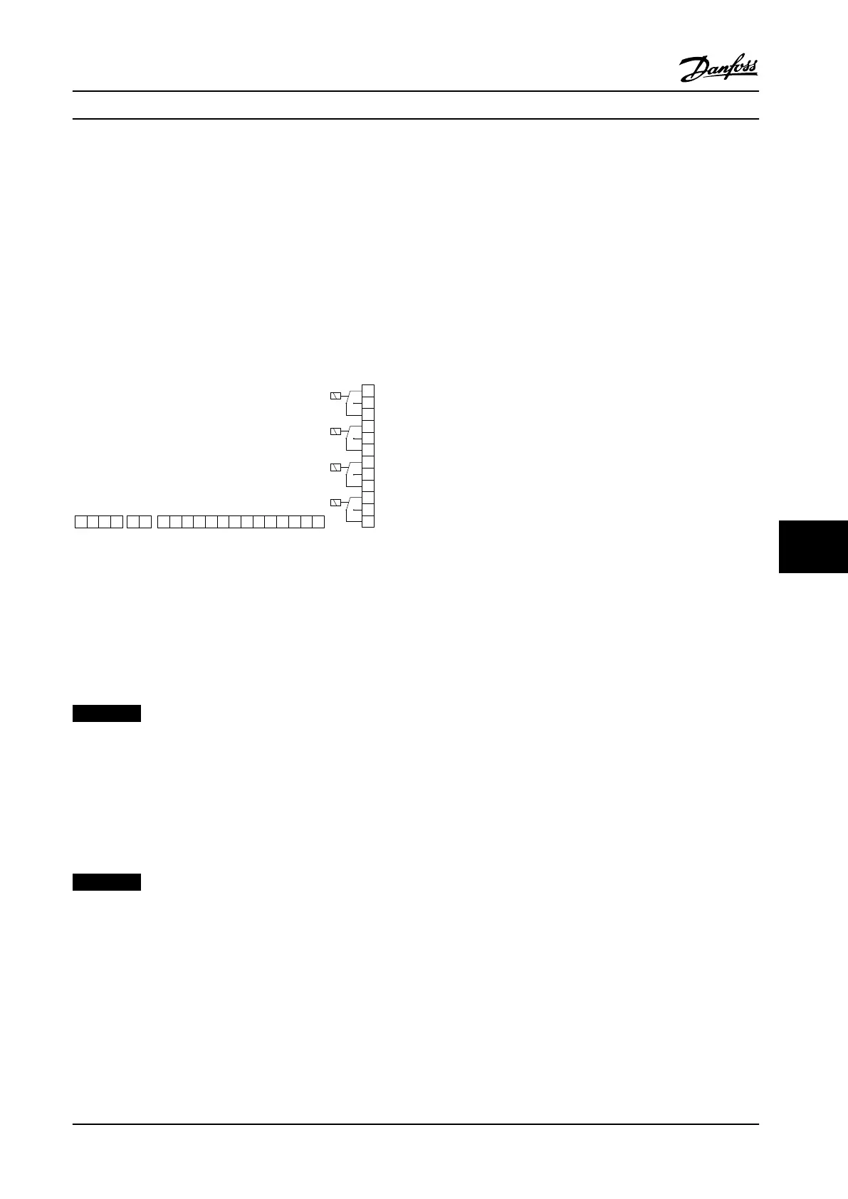
A03
A03
Ext. 24 VDC
DI1
DI2
DI3
DI4
DI5
DI6
DI7
X45/ X48/ X46/
X47/
Relay 3 Relay 4 Relay 5 Relay 6
Figure 9.17 Electrical Connections of MCB 113
MCB 113 can be connected to an external 24 V on X58/ in
order to ensure galvanic isolation between the VLT
®
AutomationDrive and the option card. If galvanic isolation
is not needed, the option card can be powered through
internal 24 V from the adjustable frequency drive.
NOTICE!
It is acceptable to combine 24 V signals with high
voltage signals in the relays as long as there is one
unused relay in-between.
To set up MCB 113, use parameter groups 5-1* Digital
Inputs, 6-7* Analog Output 3, 6-8* Analog Output 4, 14-8*
Options, 5-4* Relays, and 16-6* Inputs and Outputs.
NOTICE!
In parameter group 5-4* Relays, array [2] is relay 3, array
[3] is relay 4, array [4] is relay 5, and array [5] is relay 6.
Options and Accessories Design Guide
MG34S222 Danfoss A/S © Rev. 2014-02-10 All rights reserved. 261
9 9
 Loading...


