Parameters
Notes/Comments:
If the limit in the feedback
monitor is exceeded,
Warning 90 is issued. The
SLC monitors Warning 90
and if Warning 90 becomes
TRUE, then Relay 1 is
triggered.
External equipment may
require service. If the
feedback error goes below
the limit again within 5 sec
then the adjustable
frequency drive continues
and the warning
disappears. Press [Reset] on
the LCP to reset Relay 1.
Table 8.13 Using SLC to Set a Relay
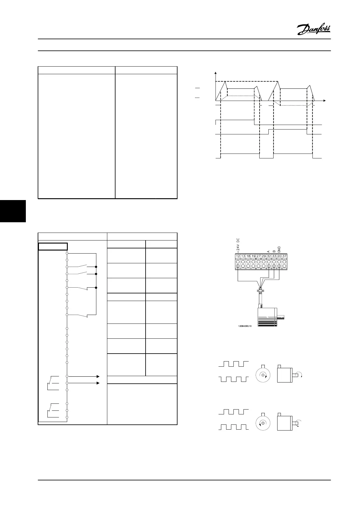
8.10 Mechanical Brake Control
Parameters
FC
+24 V
+24 V
D IN
D IN
D IN
COM
D IN
D IN
D IN
D IN
+10 V
A IN
A IN
COM
A OUT
COM
R1R2
12
13
18
19
20
27
29
32
33
37
50
53
54
55
42
39
01
02
03
04
05
06
130BB841.10
Function Setting
5-40 Function
Relay
[32] Mech.
brake ctrl.
5-10 Terminal 18
Digital Input
[8] Start*
5-11 Terminal 19
Digital Input
[11] Start
reversing
1-71 Start Delay 0.2
1-72 Start
Function
[5] VVC
plus
/
FLUX
Clockwise
1-76 Start
Current
Im,n
2-20 Release
Brake Current
App.
dependent
2-21 Activate
Brake Speed
[RPM]
Half of
nominal slip
of the motor
*=Default Value
Notes/Comments:
Table 8.14 Mechanical Brake Control
Start (18)
Start
reversing (19)
Relay output
Speed
Time
Current
1-71
1-71
2-21
2-21
1-76
Open
Closed
130BB842.10
Figure 8.4 Mechanical Brake Control
8.11 Encoder Connection
Before setting up the encoder, the basic settings for a
closed-loop speed control system is shown.
See also chapter 9.3 Encoder Option MCB 102.
Figure 8.5 Encoder Connection to the Adjustable Frequency
Drive
Figure 8.6 24 V Incremental Encoder. Maximum Cable Length
5 m
Application Examples Design Guide
246 Danfoss A/S © Rev. 2014-02-10 All rights reserved. MG34S222
88

 Loading...


