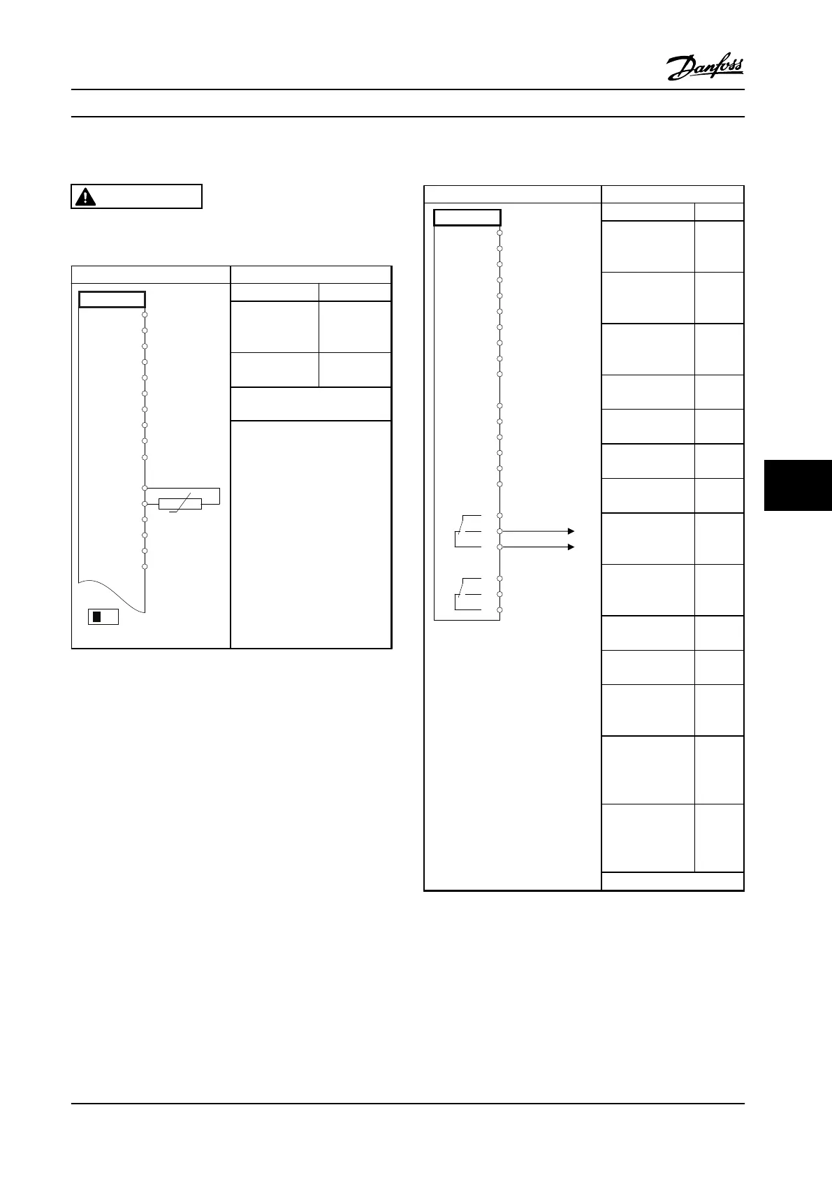
8.8 Motor Thermistor
CAUTION
Thermistors must use reinforced or double insulation to
meet PELV insulation requirements.
Parameters
130BB686.12
VLT
+24 V
+24 V
D IN
D IN
D IN
COM
D IN
D IN
D IN
+10 V
A IN
A IN
COM
A OUT
COM
12
13
18
19
20
27
29
32
33
50
53
54
55
42
39
A53
U - I
D IN
37
Function Setting
1-90 Motor
Thermal
Protection
[2]
Thermistor
trip
1-93 Thermistor
Source
[1] analog
input 53
*=Default Value
Notes/Comments:
If only a warning is desired,
1-90 Motor Thermal Protection
should be set to [1] Thermistor
warning.
Table 8.12 Motor Thermistor
8.9
Relay Set-up with Smart Logic Control
Parameters
FC
+24 V
+24 V
D IN
D IN
D IN
COM
D IN
D IN
D IN
D IN
+10 V
A IN
A IN
COM
A OUT
COM
R1R2
12
13
18
19
20
27
29
32
33
37
50
53
54
55
42
39
01
02
03
04
05
06
130BB839.10
Function Setting
4-30 Motor
Feedback Loss
Function
[1]
Warning
4-31 Motor
Feedback Speed
Error
100 RPM
4-32 Motor
Feedback Loss
Timeout
5 s
7-00 Speed PID
Feedback Source
[2] MCB
102
17-11 Resolution
(PPR)
1024*
13-00 SL
Controller Mode
[1] On
13-01 Start Event [19]
Warning
13-02 Stop Event [44]
Reset
key
13-10 Comparator
Operand
[21]
Warning
no.
13-11 Comparator
Operator
[1]*
13-12 Comparator
Value
90
13-51 SL
Controller Event
[22]
Compar
ator 0
13-52 SL
Controller Action
[32] Set
digital
out A
low
5-40 Function
Relay
[80] SL
digital
output
A
*=Default Value
Application Examples Design Guide
MG34S222 Danfoss A/S © Rev. 2014-02-10 All rights reserved. 245
8 8

 Loading...


