3.4.3 Example of How to Program the Speed Control
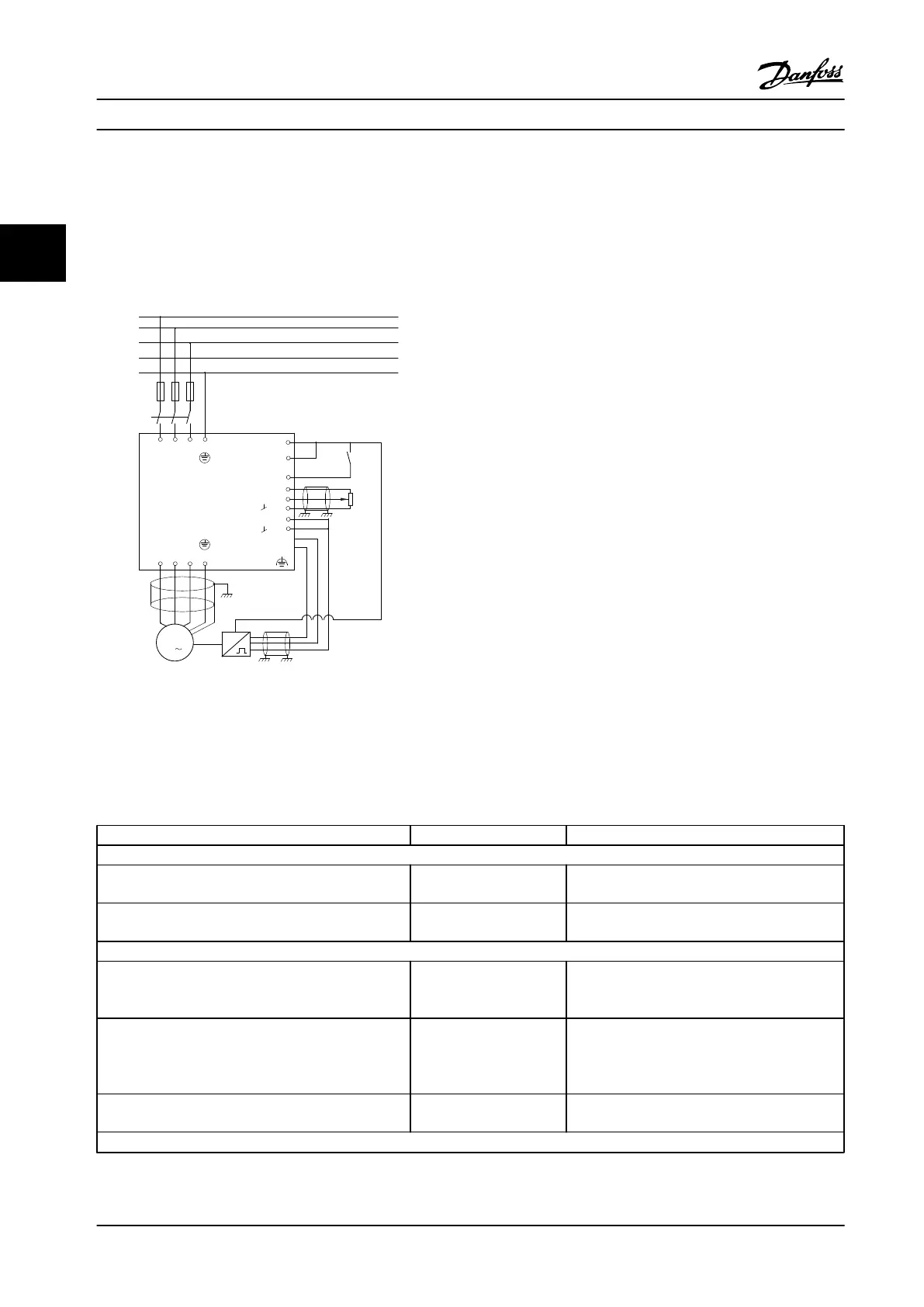
In this case, the speed PID control is used to maintain a constant motor speed regardless of the changing load on the
motor. The required motor speed is set via a potentiometer connected to terminal 53. The speed range is 0–1500 RPM
corresponding to 0–10 V over the potentiometer. Starting and stopping is controlled by a switch connected to terminal 18.
The Speed PID monitors the actual RPM of the motor by using a 24 V (HTL) incremental encoder as feedback. The feedback
sensor is an encoder (1024 pulses per revolution) connected to terminals 32 and 33.
M
3
96 97 9998
91 92 93 95
50
12
L1 L2
L1
PEL3
W PEVU
F1
L2
L3
N
PE
18
53
37
55
20
32
33
39
24 Vdc
130BA174.10
Figure 3.21 Speed Control Connections
3.4.4
Speed PID Control Programming Order
The following must be programmed in the order shown (see explanation of settings in the VLT
®
AutomationDrive
Programming Guide). In Table 3.8, it is assumed that all other parameters and switches remain at their default settings.
Function Parameter no. Setting
1) To ensure the motor runs properly, do the following:
Set the motor parameters according to the nameplate
data.
1-2* Motor Data As specified by motor nameplate
Perform Automatic Motor Adaptation (AMA). 1-29 Automatic Motor
Adaptation (AMA)
[1] Enable complete AMA
2) Check that the motor is running and that the encoder is attached properly. Do the following:
Press [Hand On]. Check that the motor is running and
note in which direction it is turning (henceforth referred
to as the “positive direction”).
Set a positive reference.
Go to 16-20 Motor Angle. Turn the motor slowly in the
positive direction. It must be turned so slowly (only a
few RPM) that it can be determined if the value in
16-20 Motor Angle is increasing or decreasing.
16-20 Motor Angle N.A. (read-only parameter) Note: An increasing
value overflows at 65,535 and starts again at 0.
If 16-20 Motor Angle is decreasing, then change the
encoder direction in 5-71 Term 32/33 Encoder Direction.
5-71 Term 32/33 Encoder
Direction
[1] Counter-clockwise (if 16-20 Motor Angle is
decreasing)
3) Make sure the drive limits are set to safe values.
Product Introduction Design Guide
38 Danfoss A/S © Rev. 2014-02-10 All rights reserved. MG34S222
33

 Loading...


