6.2.5 Terminal Locations - Frame Size F
The F-frames have four different sizes, F1, F2, F3, and F4. The F1 and F2 consist of an inverter cabinet on the right and
rectifier cabinet on the left. The F3 and F4 are F1/F2 units with an additional options cabinet to the left of the rectifier
cabinet.
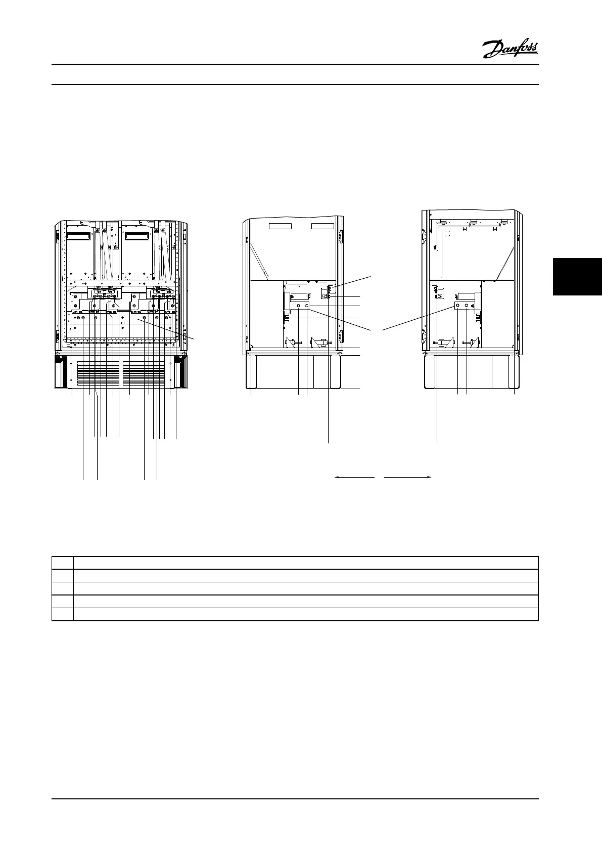
Terminal Locations - Frame Size F1 and F3
130BA849.13
.0 [.0]
54.4[2.1]
169.4 [6.7]
284.4 [11.2]
407.3 [16.0]
522.3 [20.6]
637.3 [25.1]
287.4 [11.3]
253.1 [10.0]
.0 [.0]
.0 [.0]
339.4 [13.4]
287.4 [11.3]
.0 [.0]
339.4 [13.4]
308.3 [12.1]
465.6 [18.3]
465.6 [18.3]
198.1[7.8]
234.1 [9.2]
282.1 [11.1]
318.1 [12.5]
551.0 [21.7]
587.0 [23.1]
635.0 [25.0]
671.0 [26.4]
44.40 [1.75]
244.40 [9.62]
204.1 [8.0]
497.1 [19.6]
572.1 [22.5]
180.3 [7.1]
129.1 [5.1]
4
6
4
1
2
3
5
Figure 6.67 Terminal Locations - Inverter Cabinet. Connector Plate is 1.65 in [42 mm] below .0 Level.
1
Front View
2 Left Side View
3 Right Side View
4 Brake Terminals
5 Ground bar
Table 6.35 Legend to Figure 6.67
Mechanical Installation Design Guide
MG34S222 Danfoss A/S © Rev. 2014-02-10 All rights reserved. 153
6 6

 Loading...


