6.2.9 Cooling and Airflow
Cooling
Cooling can be achieved through one of the following methods:
•
cooling ducts in the bottom and the top of the unit
•
backchannel cooling
•
combination of the cooling ducts and the backchannel cooling
Duct Cooling
A dedicated option has been developed to optimize installation of IP00/chassis adjustable frequency drives in Rittal TS8
enclosures utilizing the fan of the adjustable frequency drive for forced air cooling of the backchannel. The air out the top
of the enclosure could be ducted outside a facility so the heat losses from the backchannel are not dissipated within the
control room, reducing air conditioning requirements of the facility.
Back Cooling
The backchannel air can also be ventilated in and out the back of a Rittal TS8 enclosure. Using this method, the
backchannel could take air from outside the facility and then return the heat losses outside the facility, thus reducing air
conditioning requirements.
NOTICE!
A door fan is required on the enclosure to remove the heat losses not contained in the backchannel of the adjustable
frequency drive and any additional losses generated from other components installed inside the enclosure. The total
required air flow must be calculated so that the appropriate fans can be selected. Some enclosure manufacturers offer
software for performing the calculations.
Airflow
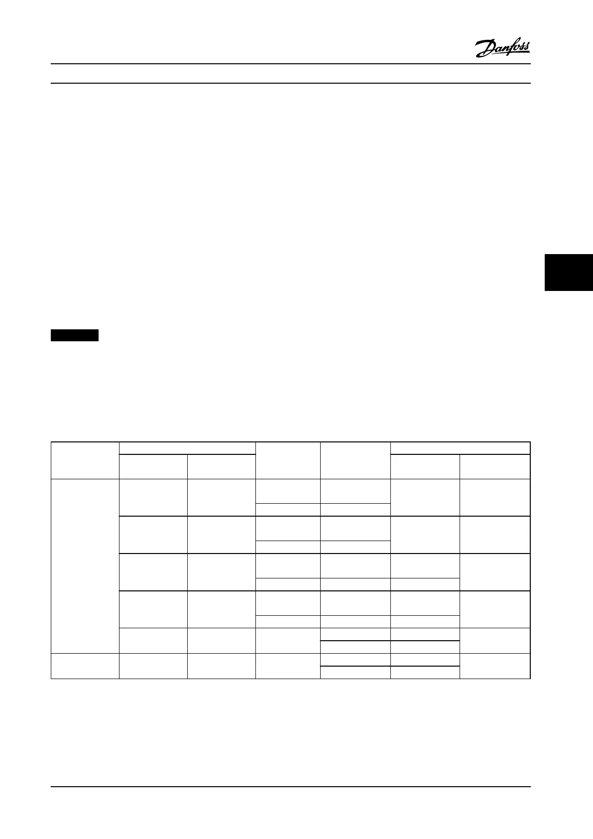
The necessary airflow over the heatsink must be ensured. The flow rate is shown in Table 6.62.
Drive type
Drive size
Frame size
Enclosure
protection
Airflow m3/h (cfm)
380–480 V (T5) 525–690 V (T7)
Door fan(s)/Top
fan
Heatsink fan(s)
6-Pulse
N110 to N160 N75 to N160
D1h, D5h, D6h
IP21/NEMA 1 or
IP54/NEMA 12
102 (60) 420 (250)
D3h IP20/chassis
N200 to N315 N200 to N400
D2h, D7h, D8h
IP21/NEMA 1 or
IP54/NEMA 12
204 (120) 840 (500)
D4h IP20/chassis
- P450 to P500
E1
IP21/NEMA 1 or
IP54/NEMA 12
340 (200)
1105 (650)
E2 IP00/chassis 255 (150)
P355 to P450 P560 to P630
E1
IP21/NEMA 1 or
IP54/NEMA 12
340 (200)
1445 (850)
E2 IP00/chassis 255 (150)
P500 to P1M0 P710 to P1M4 F1/F3, F2/F4
IP21/NEMA 1 700 (412)
985 (580)
IP54/NEMA 12 525 (309)
12-Pulse P315 to P1M0 P450 to P1M4
F8/F9, F10/F11,
F12/F13
IP21/NEMA 1 700 (412)
985 (580)
IP54/NEMA 12 525 (309)
Table 6.62 Heatsink and Front Channel Airflow
* Airflow per fan. F-frames contain multiple fans.
Mechanical Installation
Design Guide
MG34S222 Danfoss A/S © Rev. 2014-02-10 All rights reserved. 173
6 6
 Loading...


