130BB956.12
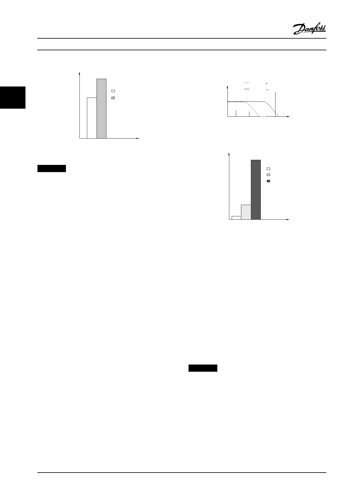
THVD=0%
THVD=5%
Leakage current
Figure 3.29 Influence of Line Distortion on Leakage Current
NOTICE!
When a filter is used, turn off 14-50 RFI 1 when charging
the filter to avoid a high leakage current making the
RCD switch.
If the leakage current exceeds 3.5 mA, EN/IEC61800-5-1
(Power Drive System Product Standard) requires that
grounding must be reinforced in one of the following
ways:
•
Ground wire (terminal 95) of at least 0.016 in
2
[10 mm
2
]
•
Two separate ground wires both complying with
the dimensioning rules
See EN/IEC61800-5-1 and EN50178 for further information.
Using RCDs
Where residual current devices (RCDs), also known as
ground leakage circuit breakers (GLCBs), are used, comply
with the following:
•
Use RCDs of type B only, capable of detecting AC
and DC currents
•
Use RCDs with a soft-charge delay to prevent
faults due to transient ground currents
•
Dimension RCDs according to the system configu-
ration and environmental considerations
See also
Protection Against Electrical Hazards.
130BB958.12
f
sw
Cable
150 Hz
3rd harmonics
50 Hz
Mains
RCD with low f
cut-
RCD with high f
cut-
Leakage current
Frequency
Figure 3.30 Main Contributions to Leakage Current
130BB957.11
Leakage current [mA]
100 Hz
2 kHz
100 kHz
Figure 3.31 Influence of the Cut-off Frequency of the RCD
What is Responded to/Measured
3.8 Brake Functions
The braking function - either static or dynamic - is used for
braking the load on the motor shaft.
3.8.1
Mechanical Holding Brake
A mechanical holding brake is an external piece of
equipment mounted directly on the motor shaft that
performs static braking. Static braking is when a brake is
used to clamp down on the motor after the load has been
stopped. A holding brake is either controlled by a PLC or
directly by a digital output from the adjustable frequency
drive.
NOTICE!
An adjustable frequency drive cannot safely control a
mechanical brake. A redundancy circuitry for the brake
control must be included in the installation.
Product Introduction Design Guide
52 Danfoss A/S © Rev. 2014-02-10 All rights reserved. MG34S222
33

 Loading...


