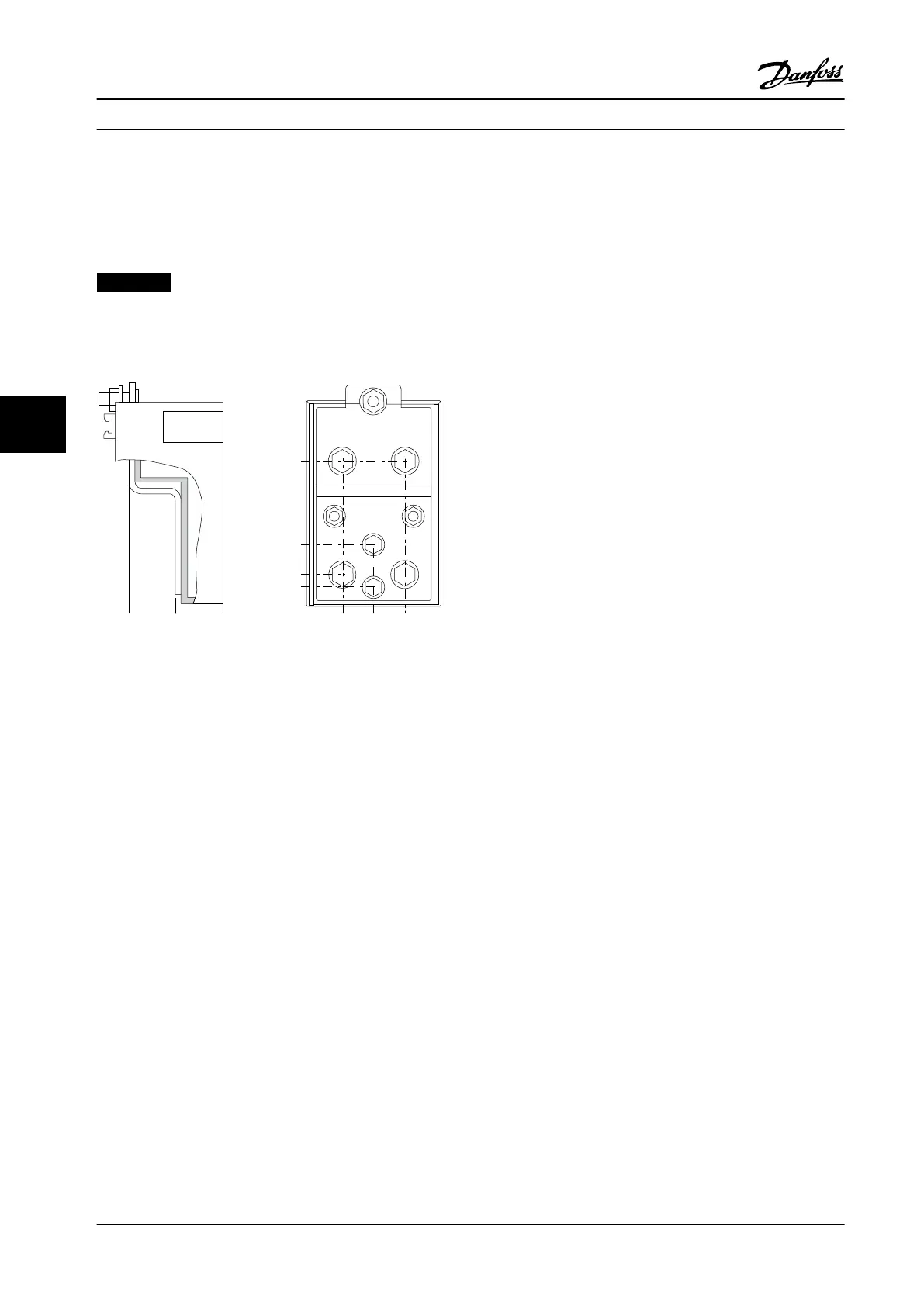
6.2.4 Terminal Locations - Frame Size E
Terminal Locations - Frame Size E1
Take the following position of the terminals into consideration when designing the cable access.
Dimensions are shown in mm [in].
NOTICE!
Power cables are heavy and hard to bend. Consider the optimum position of the adjustable frequency drive to ensure
easy installation of the cables. Each terminal allows the use of up to four cables with cable lugs or the use of a standard
box lug. Ground is connected to a relevant termination point in the adjustable frequency drive.
104[4.1]
35[1.4]
10[0.4]
0[0.0]
0[0.0]
40[1.6]
78[3.1]
0[0.0]
26[1.0]
26[1.0]
176FA271.10
Figure 6.60 Terminal in Detail
Mechanical Installation Design Guide
146 Danfoss A/S © Rev. 2014-02-10 All rights reserved. MG34S222
66

 Loading...


