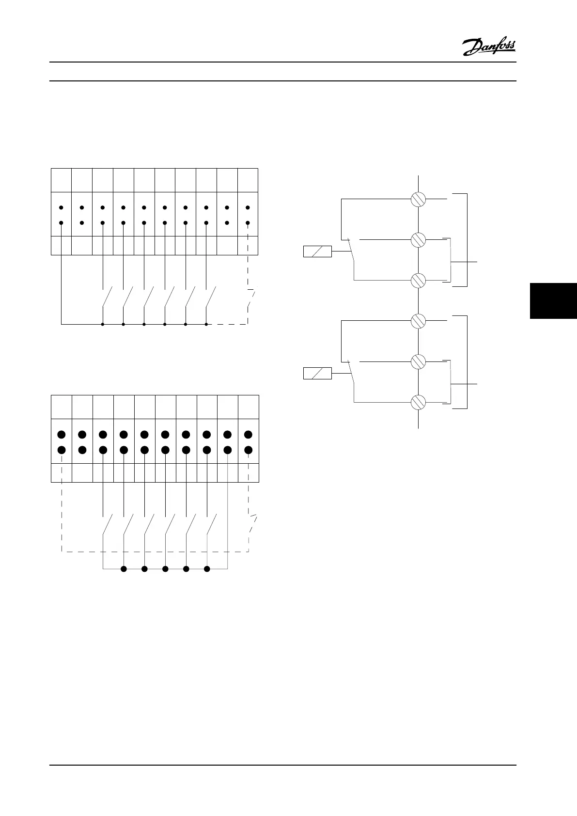
Input Polarity of Control Terminals
12 13 18 19 27 29 32 33 20 37
+24 V DC
0 VDC
130BT106.10
PNP (Source)
Digital input wiring
Figure 7.50 Input Polarity of Control Terminals
NPN (Sink)
Digital input wiring
12 13 18 19 27 29 32 33 20 37
+24 V DC
0 VDC
130BT107.11
Figure 7.51 Input Polarity of Control Terminals
7.5.9
Relay Output D Frame
Relay 1
•
Terminal 01: common
•
Terminal 02: normally open 400 V AC
•
Terminal 03: normally closed 240 V AC
Relay 2
•
Terminal 04: common
•
Terminal 05: normally open 400 V AC
•
Terminal 06: normally closed 240 V AC
Relay 1 and relay 2 are programmed in
5-40 Function Relay,
5-41 On Delay, Relay, and 5-42 Off Delay, Relay.
Use option module MCB 105 for additional relay outputs.
130BC554.10
relay1
relay2
03
02
240Vac, 2A
01
06
05
04
240Vac, 2A
400Vac, 2A
400Vac, 2A
Figure 7.52 D-Frame Additional Relay Outputs
7.5.10
Relay Output E & F-Frame
Relay 1
•
Terminal 01: common
•
Terminal 02: normally open 240 V AC
•
Terminal 03: normally closed 240 V AC
Relay 2
•
Terminal 04: common
•
Terminal 05: normally open 400 V AC
•
Terminal 06: normally closed 240 V AC
Relay 1 and relay 2 are programmed in 5-40 Function Relay,
5-41 On Delay, Relay, and 5-42 Off Delay, Relay.
Use option module MCB 105 for additional relay outputs.
Electrical Installation
Design Guide
MG34S222 Danfoss A/S © Rev. 2014-02-10 All rights reserved. 231
7 7

 Loading...


