10 RS-485 Installation and Set-up
10.1 Overview
RS-485 is a 2-wire bus interface compatible with multi-drop
network topology. Nodes can be connected as a bus, or
via drop cables from a common trunk line. A total of 32
nodes can be connected to one network segment.
Repeaters divide network segments. Note each repeater
function as a node within the segment in which it is
installed. Each node connected within a given network
must have a unique node address across all segments.
Terminate each segment at both ends, using either the
termination switch (S801) of the adjustable frequency
drives or a biased termination resistor network. Always use
shielded twisted pair (STP) cable for bus cabling, and
always follow good common installation practice.
Low-impedance ground connection of the shield at every
node is important, including at high frequencies. Thus,
connect a large surface of the shield to ground, e.g., with a
cable clamp or a conductive cable connector. If necessary,
apply potential-equalizing cables to maintain the same
ground potential throughout the network. Particularly in
installations with long cables.
To prevent impedance mismatch, always use the same
type of cable throughout the entire network. When
connecting a motor to the adjustable frequency drive,
always use shielded motor cable.
Cable
Shielded twisted pair (STP)
Impedance
120 Ω
Cable length Max. 4,000 ft [1,200 m] (including drop lines)
Max. 1,650 ft [500 m] station-to-station
Table 10.1 Motor Cable
10.2
Network Connection
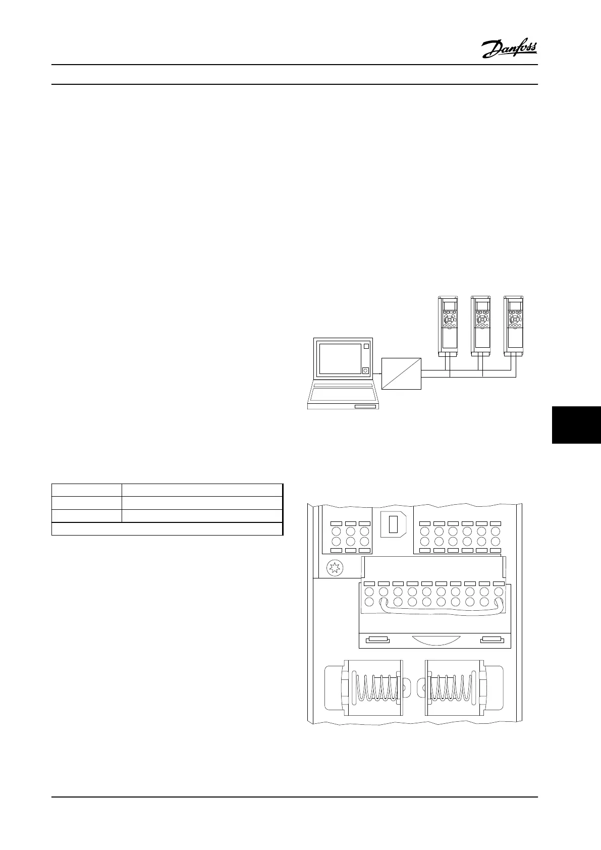
One or more adjustable frequency drives can be connected
to a control (or master) using the RS-485 standardized
interface. Terminal 68 is connected to the P signal (TX+, RX
+), while terminal 69 is connected to the N signal (TX-,
RX-). See figures in chapter 7.7.2 Grounding
If more than one adjustable frequency drive is connected
to a master, use parallel connections.
130BA060.11
68 69 68 69 68 69
RS 485
RS 232
USB
+
-
Figure 10.1 Parallel Connections
To avoid potential equalizing currents in the shield, ground
the cable shield via terminal 61, which is connected to the
frame via an RC link.
130BB021.10
12 13 18 19 27 29 32
33 20 37
Remove jumper to enable Safe Stop
61 68 69 39 42 50 53 54 55
Figure 10.2 Control Card Terminals
RS-485 Installation and Set... Design Guide
MG34S222 Danfoss A/S © Rev. 2014-02-10 All rights reserved. 267
10 10

 Loading...


