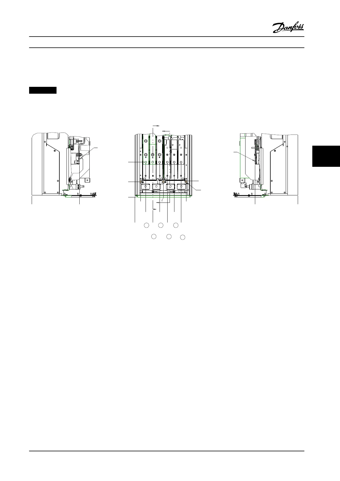
6.2.3 Terminal Locations - Frame Size D
Take the following terminal positions into consideration when designing for cable access. Dimensions are shown in mm [in].
NOTICE!
Power cables are heavy and hard to bend. Consider the optimum position of the adjustable frequency drive to ensure
easy installation of the cables.
A
A
B
B
33
1.3[ ]
0
0.0[ ]
62
2.4[ ]
101
4.0[ ]
140
5.5[ ]
163
6.4[ ]
185
7.3[ ]
224
8.8[ ]
263
10.4[ ]
293
11.5[ ]
GROUND 88
3.5[ ]
0
0.0[ ]
200
7.9[ ]
94
3.7[ ]
244
9.6[ ]
0
0.0[ ]
272
10.7[ ]
0
0.0[ ]
S
U
W
R T V
3X M8x20 STUD
WITH NUT
SECTION A-A
MAINS TERMINALS
MAINS TERMINAL
SECTION B-B
MOTOR TERMINALS
MOTOR
TERMINAL
130BC305.10
Figure 6.46 Position of Power Connections, Frame Size D1h
Mechanical Installation Design Guide
MG34S222 Danfoss A/S © Rev. 2014-02-10 All rights reserved. 133
6 6

 Loading...


