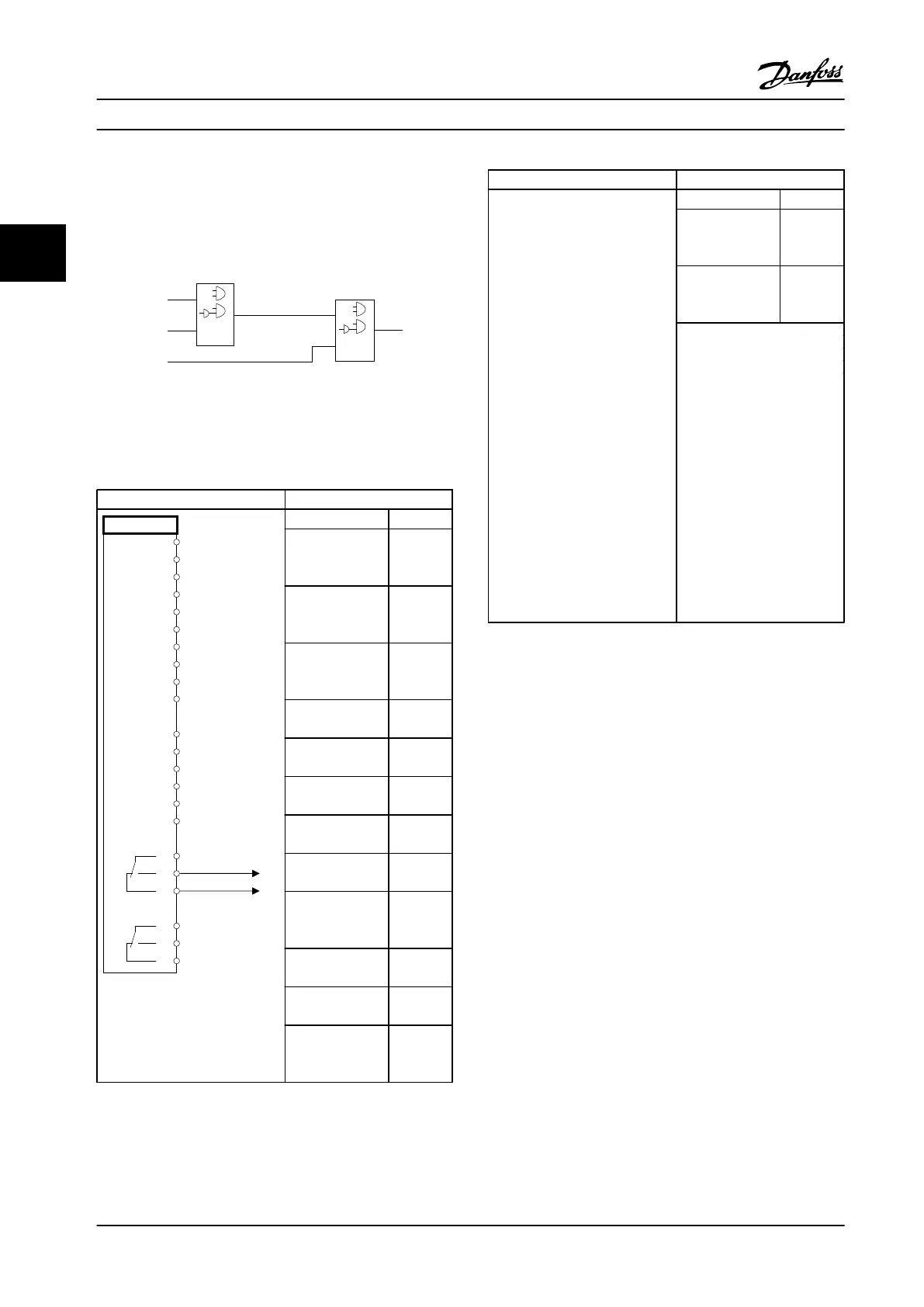
Logic rules
Combine up to three Boolean (TRUE/FALSE) inputs from
timers, comparators, digital inputs, status bits and events
using the logical operators AND, OR, and NOT.
. . .
. . .
. . .
. . .
Par. 13-43
Logic Rule Operator 2
Par. 13-41
Logic Rule Operator 1
Par. 13-40
Logic Rule Boolean 1
Par. 13-42
Logic Rule Boolean 2
Par. 13-44
Logic Rule Boolean 3
130BB673.10
Figure 3.38 Logic Rules
Application example
Parameters
FC
+24 V
+24 V
D IN
D IN
D IN
COM
D IN
D IN
D IN
D IN
+10 V
A IN
A IN
COM
A OUT
COM
R1R2
12
13
18
19
20
27
29
32
33
37
50
53
54
55
42
39
01
02
03
04
05
06
130BB839.10
Function Setting
4-30 Motor
Feedback Loss
Function
[1]
Warning
4-31 Motor
Feedback Speed
Error
100 RPM
4-32 Motor
Feedback Loss
Timeout
5 s
7-00 Speed PID
Feedback Source
[2] MCB
102
17-11 Resolution
(PPR)
1024*
13-00 SL
Controller Mode
[1] On
13-01 Start Event [19]
Warning
13-02 Stop Event [44]
Reset key
13-10 Comparator
Operand
[21]
Warning
no.
13-11 Comparator
Operator
[1] ≈*
13-12 Comparator
Value
90
13-51 SL
Controller Event
[22]
Comparat
or 0
Parameters
Function Setting
13-52 SL
Controller Action
[32] Set
digital out
A low
5-40 Function
Relay
[80] SL
digital
output A
Notes/Comments:
If the limit in the feedback
monitor is exceeded, Warning
90 will be issued. The SLC
monitors Warning 90 and if
Warning 90 becomes TRUE,
then Relay 1 is triggered.
External equipment may then
indicate that service may be
required. If the feedback
error goes below the limit
again within 5 s, the drive
continues and the warning
disappears. But Relay 1 will
still be triggered until [Reset]
on the LCP.
Table 3.20 Using SLC to Set a Relay
3.11
Extreme Running Conditions
Short Circuit (Motor Phase – Phase)
The adjustable frequency drive is protected against short
circuits by means of current measurement in each of the
three motor phases or in the DC link. A short circuit
between two output phases causes an overcurrent in the
inverter. The inverter turns off individually when the short
circuit current exceeds the permitted value (Alarm 16 Trip
Lock).
To protect the adjustable frequency drive against a short
circuit at the load sharing and brake outputs, see
Application Note for FC 100, FC 200 and FC 300 Fuses and
Circuit Breakers.
See certificate in .
Switching on the Output
Switching on the output between the motor and the
adjustable frequency drive is fully permitted. Switching on
the output does not damage the adjustable frequency
drive, but fault messages may appear.
Product Introduction
Design Guide
60 Danfoss A/S © Rev. 2014-02-10 All rights reserved. MG34S222
33

 Loading...


