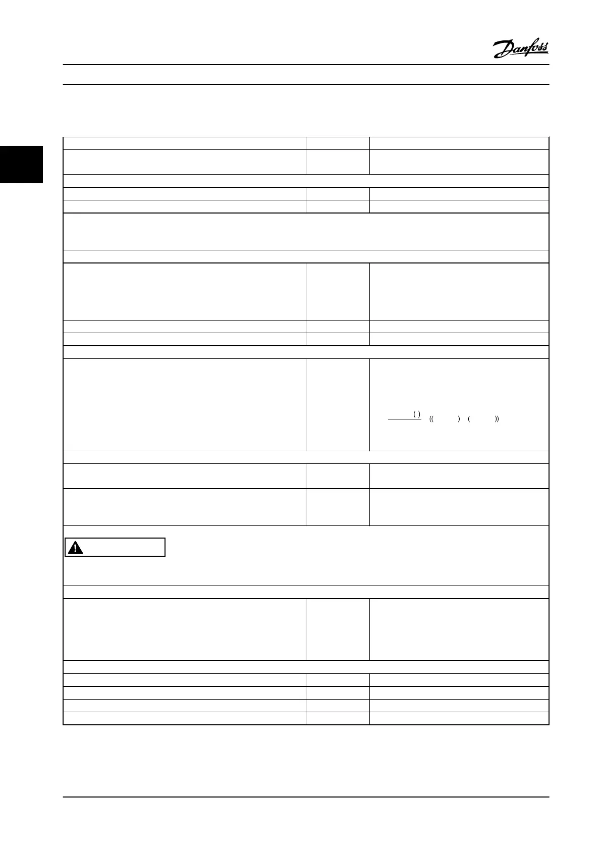
3.4.9 Process PID Control Programming Order
Function Par. no. Setting
Initialize the adjustable frequency drive. 14-22 [2] Initialization - make a power cycling - press
[Reset]
1) Set motor parameters:
Set the motor parameters according to the nameplate data. 1-2* As stated on motor nameplate
Perform a full Automation Motor Adaptation.
1-29 [1] Enable complete AMA
2) Check that motor is running in the right direction.
When the motor is connected to adjustable frequency drive with straight forward phase order as U - U; V- V; W - W, the motor shaft
usually turns clockwise as viewed from the shaft end.
Press the [Hand On] LCP key. Check the shaft direction by applying a manual reference.
If the motor turns opposite of the required direction:
1.
Change motor direction in 4-10 Motor Speed Direction
2. Turn off line power - wait for DC link to discharge - switch two
of the motor phases
4-10 Select correct motor shaft direction.
Set configuration mode. 1-00 [3] Process
Set Local Mode Configuration. 1-05 [0] Speed Open-loop
3) Set reference configuration, i.e., the range for reference handling. Set scaling of analog input in parameter 6-**
Set reference/feedback units:
Set min. reference (50 °F [10 °C]):
Set max. reference (176 °F [80 °C]):
If set value is determined from a preset value (array parameter), set
other reference sources to No Function.
3-01
3-02
3-03
3-10
[60] °C] Unit shown on display
23 °F [-5 °C]
95 °F [35 °C]
[0] 35%
Ref
=
Par
. 3 − 10
0
100
×
Par
. 3 − 03 −
par
. 3 − 02 = 24, 5°
C
3-14 Preset Relative Reference to 3-18 Relative
Scaling Reference Resource [0]=No Function
4) Adjust limits for the adjustable frequency drive:
Set ramp times to an appropriate value as 20 s. 3-41
3-42
20 s
20 s
Set min. speed limits:
Set motor speed max. limit:
Set max. output frequency:
4-11
4-13
4-19
300 RPM
1500 RPM
60 Hz
Set S201 or S202 to desired analog input function (Voltage (V) or milliamps (I)):
WARNING
Switches are sensitive - Make a power cycling keeping default setting of V.
5) Scale analog inputs used for reference and feedback
Set terminal 53 low voltage:
Set terminal 53 high voltage:
Set terminal 54 low feedback value:
Set terminal 54 high feedback value:
Set feedback source:
6-10
6-11
6-24
6-25
7-20
0 V
10 V
23 °F [-5 °C]
95 °F [35 °C]
[2] analog input 54
6) Basic PID settings.
Process PID normal/inverse. 7-30 [0] Normal
Process PID anti wind-up. 7-31 [1] On
Process PID start speed. 7-32 300 rpm
Save parameters to LCP. 0-50 [1] All to LCP
Table 3.11 Example of Process PID Control Set-up
Product Introduction
Design Guide
44 Danfoss A/S © Rev. 2014-02-10 All rights reserved. MG34S222
33

 Loading...


