10.3 Bus Termination
The RS-485 bus must be terminated by using a resistor
network at both ends. For this purpose, set switch S801 on
the control card to "ON". For more information, see
chapter 7.5.4 Switches S201 (A53), S202 (A54), and S801.
Communication protocol must be set to 8-30 Protocol.
10.4 RS-485 Installation and Set-up
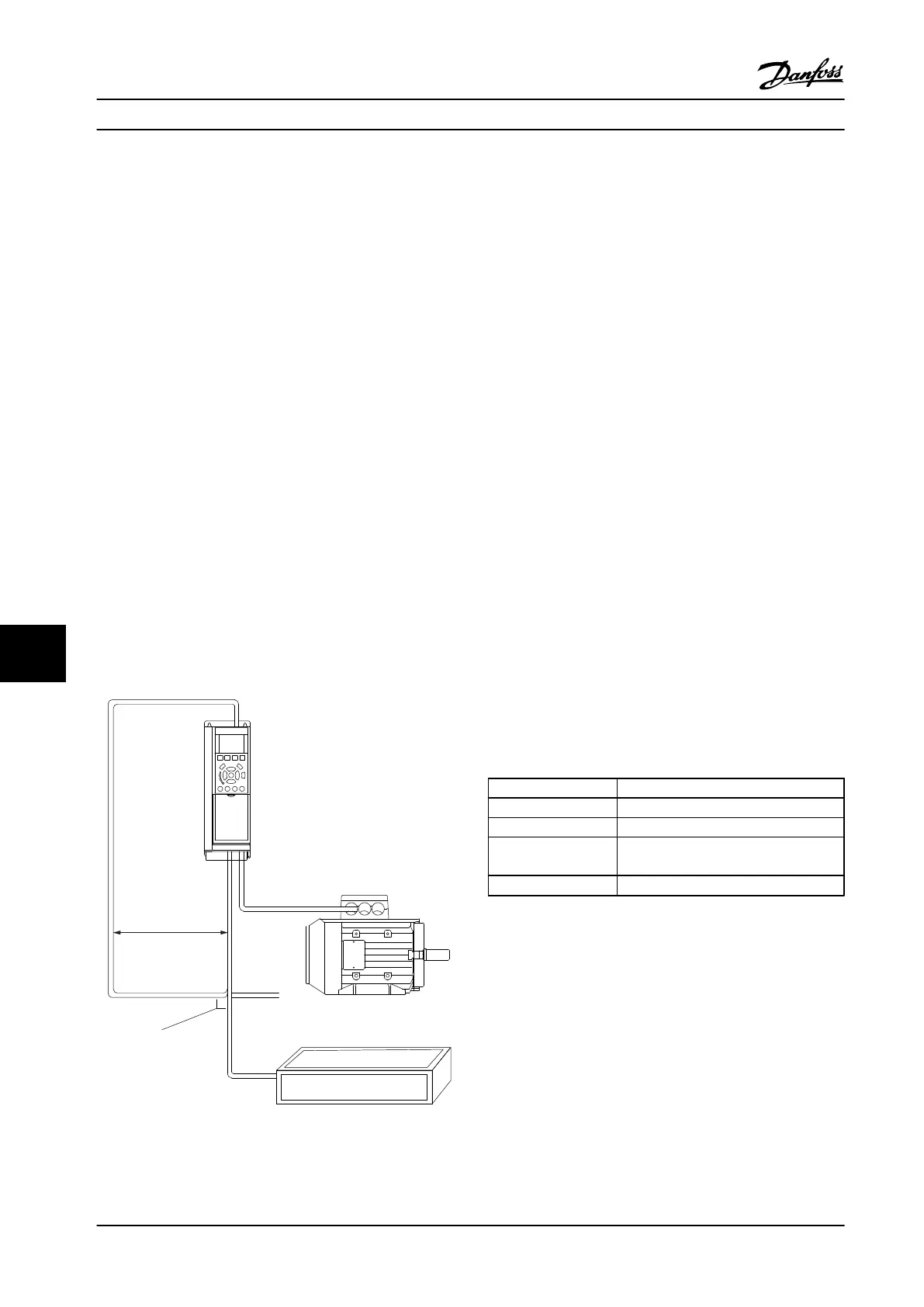
10.4.1 EMC Precautions
To achieve interference-free operation of the RS-485
network, the following EMC precautions are recommended.
Relevant national and local regulations, regarding
protective ground connection, for example, must be
observed. The RS-485 communication cable must be kept
away from motor and brake resistor cables to avoid
coupling of high-frequency noise from one cable to
another. Normally a distance of 200 mm (8 in) is sufficient.
However, in situations where cables run in parallel over
long distances, keeping the greatest possible distance
between cables is recommended. When crossing is
unavoidable, the RS-485 cable must cross motor and brake
resistor cables at an angle of 90°.
Serial com. bus cable
Brake resistor
Min. 200mm
90° crossing
130BA080.10
Figure 10.3 EMC Precautions
10.5
FC Protocol Overview
The FC protocol, also referred to as FC bus or Standard
bus, is the Danfoss standard serial communication bus. It
defines an access technique according to the master/
follower principle for communications via a serial bus.
One master and a maximum of 126 followers can be
connected to the bus. The master selects the individual
followers via an address character in the message. A
follower itself can never transmit without first being
requested to do so, and direct message transfer between
the individual followers is not possible. Communications
occur in the half-duplex mode.
The master function cannot be transferred to another node
(single-master system).
The physical layer is RS-485, thus utilizing the RS-485 port
built into the adjustable frequency drive. The FC protocol
supports different message formats:
•
A short format of 8 bytes for process data
•
A long format of 16 bytes that also includes a
parameter channel
•
A format used for texts
10.6
Network Configuration
10.6.1 Adjustable Frequency Drive Set-up
Set the following parameters to enable the FC protocol for
the adjustable frequency drive.
Parameter number Setting
8-30 Protocol FC
8-31 Address 1–126
8-32 FC Port Baud
Rate
2400–115200
8-33 Parity / Stop Bits Even parity, 1 stop bit (default)
Table 10.2 FC Protocol Parameters
RS-485 Installation and Set... Design Guide
268 Danfoss A/S © Rev. 2014-02-10 All rights reserved. MG34S222
1010

 Loading...


