NOTICE!
Change the switch position at power off only.
Figure 7.41 Location of Switches S801, S201, and S202 (Left to
Right)
7.5.5
Installing Control Terminals
Control Terminals
To mount the cable to the terminal, perform the following
steps:
1. Strip insulation of 0.34–0.39 in [9–10 mm].
2. Insert a screwdriver (max. 0.016x0.1 in [0.4x2.5
mm]) in the square hole.
3. Insert the cable in the adjacent circular hole.
4. Remove the screwdriver. The cable is now
mounted to the terminal.
To remove the cable from the terminal, perform the
following steps:
1. Insert a screwdriver (max. 0.016x0.1 in [0.4x2.5
mm]) in the square hole.
2. Pull out the cable.
7.5.6
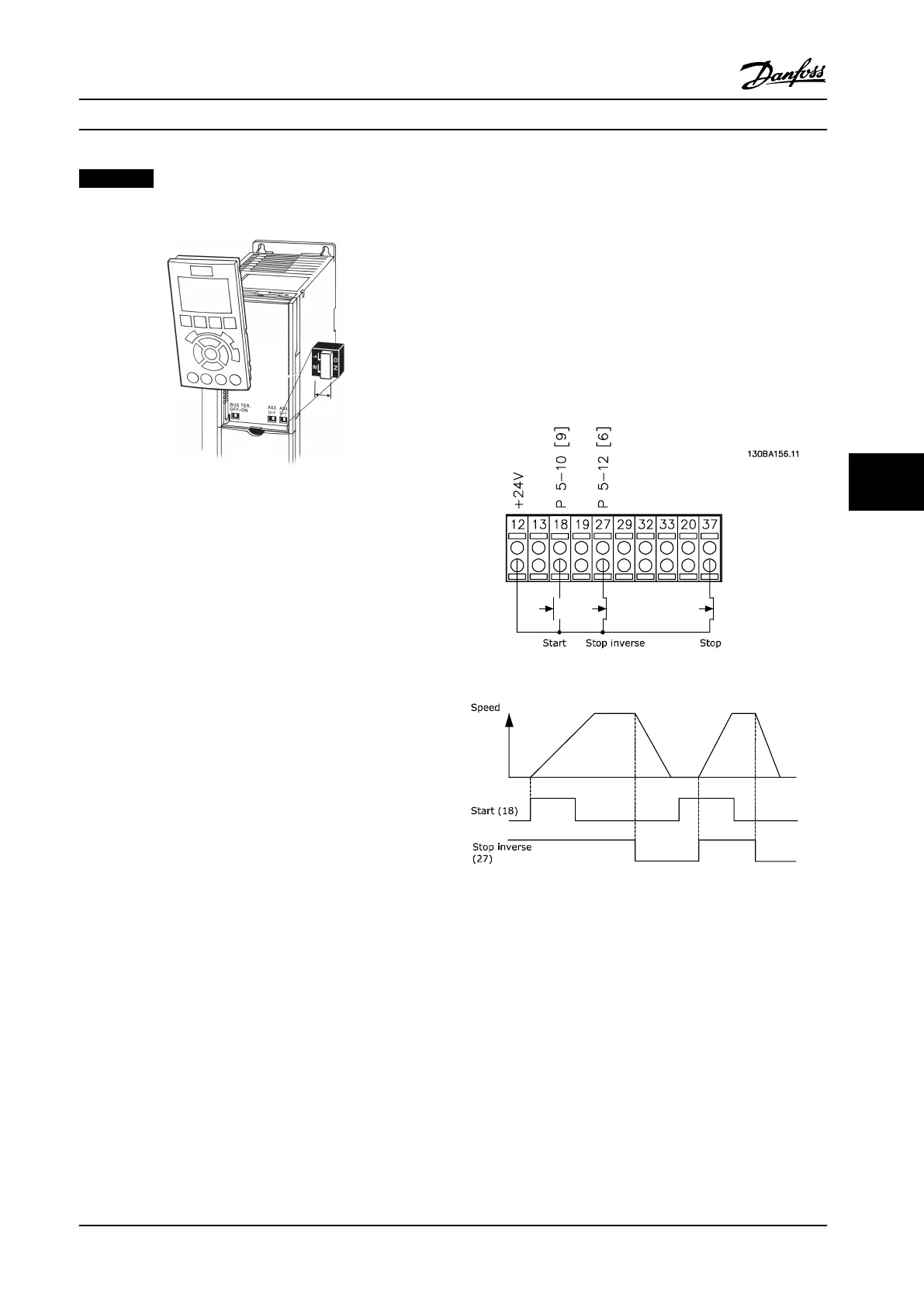
Basic Wiring Example
1. Mount the terminals from the accessory bag to
the front of the adjustable frequency drive.
2. Connect terminals 18, 27, and 37 to +24 V
(terminal 12/13)
Default Settings:
18=Start, 5-10 Terminal 18 Digital Input [9]
27=Stop inverse, 5-12 Terminal 27 Digital Input [6]
37=Safe torque off inverse
Figure 7.42 Basic Wiring
Electrical Installation Design Guide
MG34S222 Danfoss A/S © Rev. 2014-02-10 All rights reserved. 225
7 7

 Loading...


