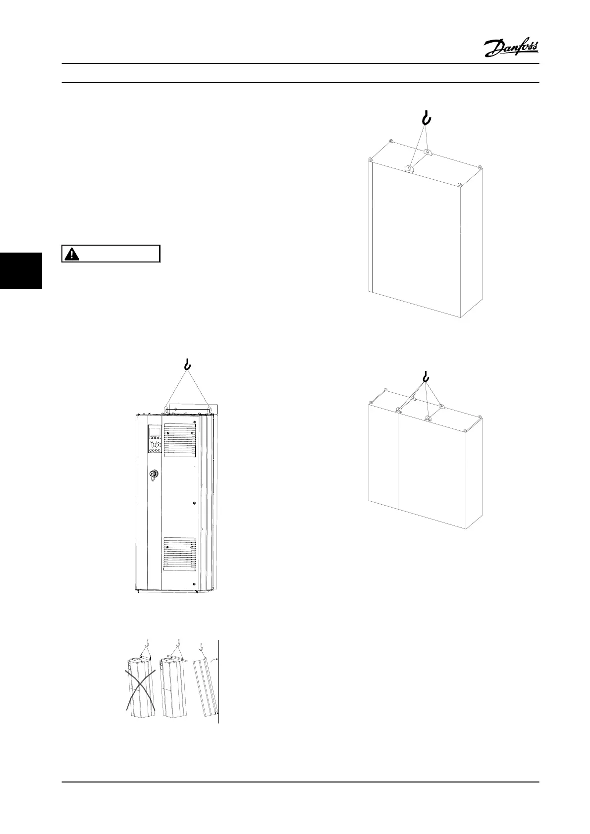
6.1.3 Lifting
Lift the adjustable frequency drive using the dedicated
lifting eyes. For all E2 (IP00) enclosures, use a bar to avoid
bending the lifting holes of the adjustable frequency drive.
The following figures demonstrate the recommended
lifting methods for the different frame sizes. In addition to
Figure 6.4, Figure 6.5, and Figure 6.6, a spreader bar is an
acceptable way to lift the F-frame.
WARNING
The lifting bar must be able to handle the weight of the
adjustable frequency drive. See chapter 6.1.4 Mechanical
Dimensions for the weight of each frame size. Maximum
diameter for the bar is 1 in [2.5 cm]. The angle from the
top of the drive to the lifting cable should be 60° or
greater.
Figure 6.2 Recommended Lifting Method, D-frame Size
Figure 6.3 Recommended Lifting Method, E-frame Size
Figure 6.4 Recommended Lifting Method, Frame Sizes F1, F2,
F9 and F10
Figure 6.5 Recommended Lifting Method, Frame Sizes F3, F4,
F11, F12 and F13
Mechanical Installation Design Guide
110 Danfoss A/S © Rev. 2014-02-10 All rights reserved. MG34S222
66

 Loading...


