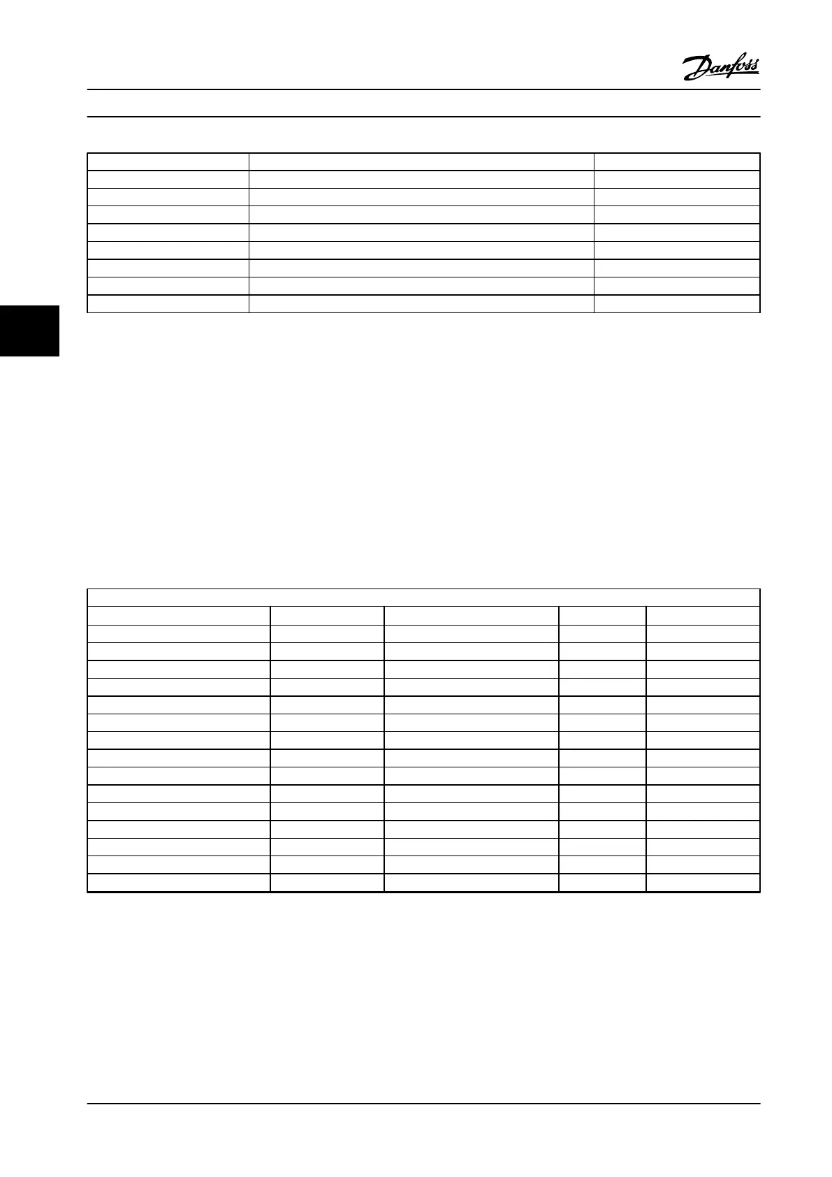
Type Description Ordering no.
PC software
MCT 10 MCT 10 Set-up Software - 1 user 130B1000
MCT 10 MCT 10 Set-up Software - 5 users 130B1001
MCT 10 MCT 10 Set-up Software - 10 users 130B1002
MCT 10 MCT 10 Set-up Software - 25 users 130B1003
MCT 10 MCT 10 Set-up Software - 50 users 130B1004
MCT 10 MCT 10 Set-up Software - 100 users 130B1005
MCT 10 MCT 10 Set-up Software - unlimited users 130B1006
Table 5.8 Software Options
Options can be ordered as factory built-in options. For information on serial communication bus and application option compatibility with older
software versions, contact the Danfoss supplier.
5.2.2
Brake Resistors
The requirements for brake resistors vary in different applications. Always consult the VLT FC Series Brake Resistor Design
Guide before selecting brake resistors. Critical data includes:
•
Brake duty cycle, resistance and brake resistor power capability
•
Adjustable frequency drive minimum resistance
The tables below present typical data for two common application types. 10% is typically used for occasional braking of
horizontal loads. 40% is typically used in lifting applications where the load must be stopped every time it is lowered.
380–500 V AC
FC 302 [T5] Pm (HO) (hp [kW])
Number of brake choppers
(1)
R
min
R
br,nom
N90K 125 [90] 1 3.6 3.8
N110 150 [110] 1 3.0 3.2
N132 175 [132] 1 2.5 2.5
N160 225 [160] 1 2.0 2.0
N200 275 [200] 1 1.6 1.7
N250 350 [250] 1 1.2 1.4
P315 425 [315] 1 1.2 1.5
P355 475 [355] 1 1.2 1.3
P400 550 [400] 1 1.1 1.1
P450 600 [450] 2 0.9 1.0
P500 650 [500] 2 0.9 0.91
P560 750 [560] 2 0.8 0.82
P630 850 [630] 2 0.7 0.72
P710 950 [710] 3 0.6 0.64
P800 1075 [800] 3 0.5 0.57
Table 5.9 Brake Chopper Data, 380–500 V
R
min
=Minimum brake resistance that can be used with this adjustable frequency drive. If the adjustable frequency drive includes multiple brake
choppers, the resistance value is the sum of all resisters in parallel.
R
br,nom
=Nominal resistance required to achieve 150% braking torque.
R
rec
=Resistance value of the recommended Danfoss brake resistor.
1)
Larger adjustable frequency drives include multiple inverter modules with a brake chopper in each inverter. Equal resistors should be connected
to each brake chopper.
How to Order
Design Guide
96 Danfoss A/S © Rev. 2014-02-10 All rights reserved. MG34S222
55
 Loading...


