6.2.7 Connector/Conduit Entry - IP21
(NEMA 1) and IP54 (NEMA12)
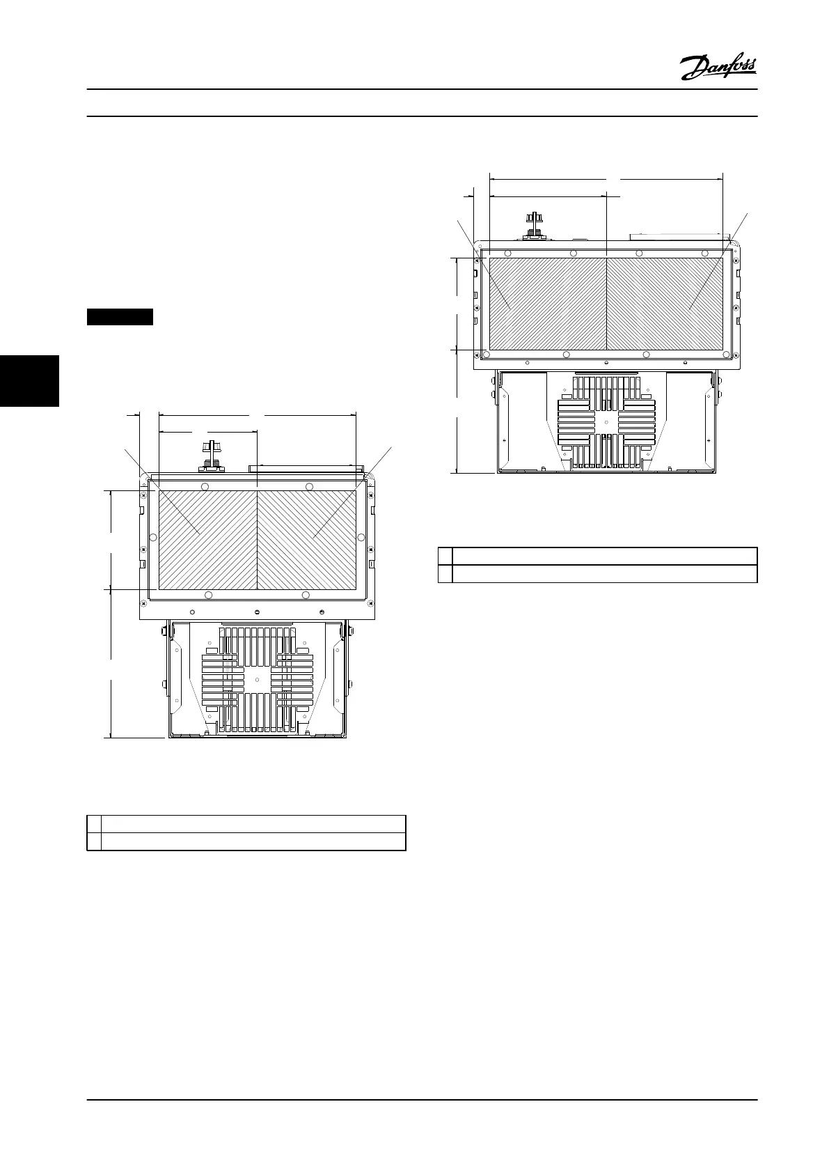
Cables are connected through the connector plate from
the bottom. Remove the plate and plan where to place the
entry for the connectors or conduits. The following figures
show the cable entry points viewed from the bottom of
various adjustable frequency drives.
NOTICE!
The connector plate must be fitted to the adjustable
frequency drive to ensure the specified degree of
protection.
130BC521.10
205
[8.1]
138
[5.4]
274
[10.8]
27
[1.0]
137
[5.4]
1
2
Figure 6.80 D1h, Bottom View 1) Line Power Side 2) Motor
Side
1
Line Power Side
2 Motor Side
Table 6.47 Legend to Figure 6.80
130BC524.11
196
[7.7]
145
[5.7]
27
[1.0]
185
[7.3]
1
2
369
[14.5]
Figure 6.81 D2h, Bottom View
1 Line Power Side
2 Motor Side
Table 6.48 Legend to Figure 6.81
Mechanical Installation Design Guide
164 Danfoss A/S © Rev. 2014-02-10 All rights reserved. MG34S222
66

 Loading...


