In Figure 3.6, 1-01 Motor Control Principle is set to [3] Flux w
motor feedb and 1-00 Configuration Mode is set to [1] Speed
closed-loop.
The motor control in this configuration relies on a
feedback signal from an encoder mounted directly on the
motor (set in 1-02 Flux Motor Feedback Source).
To use the resulting reference as an input for the Speed
PID control, select [1] Speed closed-loop in 1-00 Configu-
ration Mode. The Speed PID control parameters are located
in parameter group 7-0* Speed PID Ctr.
Select [2] Torque in 1-00 Configuration Mode to use the
resulting reference directly as a torque reference. Torque
control can only be selected in the Flux with motor
feedback (1-01 Motor Control Principle) configuration. When
this mode has been selected, the reference uses the Nm
unit. It requires no torque feedback, since the actual
torque is calculated on the basis of the current
measurement of the adjustable frequency drive.
To use the process PID control for closed-loop control of
speed or a process variable in the controlled application,
for example, select [3] Process in 1-00 Configuration Mode.
3.2.5
Internal Current Control in VVC
plus
Mode
The adjustable frequency drive features an integral current
limit control which is activated when the motor current,
and thus the torque, is higher than the torque limits set in
4-16 Torque Limit Motor Mode, 4-17 Torque Limit Generator
Mode, and 4-18 Current Limit.
When the adjustable frequency drive is at the current limit
during motor operation or regenerative operation, it tries
to get below the preset torque limits as quickly as possible
without losing control of the motor.
3.2.6
Control Local [Hand On] and Remote
[Auto On] Control
The adjustable frequency drive can be operated manually
via the LCP or remotely via analog and digital inputs and
serial bus. If allowed in 0-40 [Hand on] Key on LCP,
0-41 [Off] Key on LCP, 0-42 [Auto on] Key on LCP, and
0-43 [Reset] Key on LCP, it is possible to start and stop the
adjustable frequency drive via the LCP [Hand On] and [Off].
Press [Reset] to reset the alarms. After pressing [Hand On],
the adjustable frequency drive goes into H (manual) mode
and follows (as default) the local reference that can be set
using the arrow keys on the LCP.
After pressing [Auto On], the adjustable frequency drive
goes into Auto mode and follows (as default) the remote
reference. In this mode, it is possible to control the
adjustable frequency drive via the digital inputs and
various serial interfaces (RS-485, USB, or an optional serial
communication bus). See more about starting, stopping,
changing ramps and parameter set-ups etc. in parameter
group 5-1* Digital Inputs or parameter group 8-5* Serial
Communication.
130BP046.10
Hand
on
O
Auto
on
Reset
Figure 3.7 LCP Control Keys
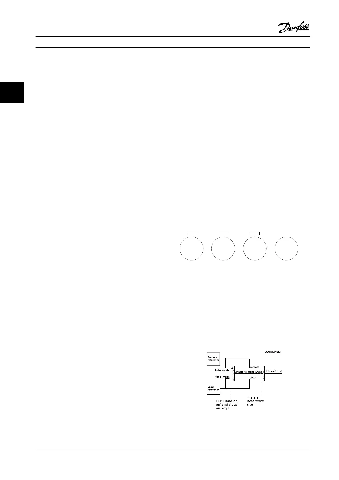
Active Reference and Configuration Mode
The active reference can be either the local reference or
the remote reference.
The local reference can be permanently selected by
selecting [2] Local in 3-13 Reference Site.
To permanently select the remote reference, select [1]
Remote. By selecting [0] Linked to Hand/Auto (default) the
reference site will depend on whether Hand or Auto mode
is active.
Figure 3.8 Active Reference
Product Introduction Design Guide
28 Danfoss A/S © Rev. 2014-02-10 All rights reserved. MG34S222
33

 Loading...


