7.9 Line Power Supply Interference/
Harmonics
An adjustable frequency drive takes up a non-sinusoidal
current from the line power, which increases the input
current I
RMS
. A non-sinusoidal current is transformed by
means of a Fourier analysis and split into sine-wave
currents with different frequencies. See Table 7.75.
Harmonic currents I
1
I
5
I
7
Hz 50 Hz 250 Hz 350 Hz
Table 7.75 Non-Sinusoidal Current Split into Sine-Wave Currents
with Different Frequencies
The harmonics do not affect the power consumption
directly, but increase the heat losses in the transformer
and cables. Therefore, in plants with a high percentage of
rectifier load, it is necessary to maintain harmonic currents
at a low level to avoid overload of the transformer and
high temperature in the cables.
NOTICE!
Some of the harmonic currents might disturb communi-
cation equipment connected to the same transformer or
cause resonance in connection with power-factor
correction batteries.
Harmonic current Input current
I
RMS
1.0
I
1
0.9
I
5
0.4
I
7
0.2
I
11-49
<0.1
Table 7.76 Harmonic Currents Compared to the RMS
Input Current
To ensure low harmonic currents, the adjustable frequency
drive is equipped with intermediate circuit coils as
standard. DC coils reduce the total harmonic distortion
(THD) to 40%.
7.9.1
The Effect of Harmonics in a Power
Distribution System
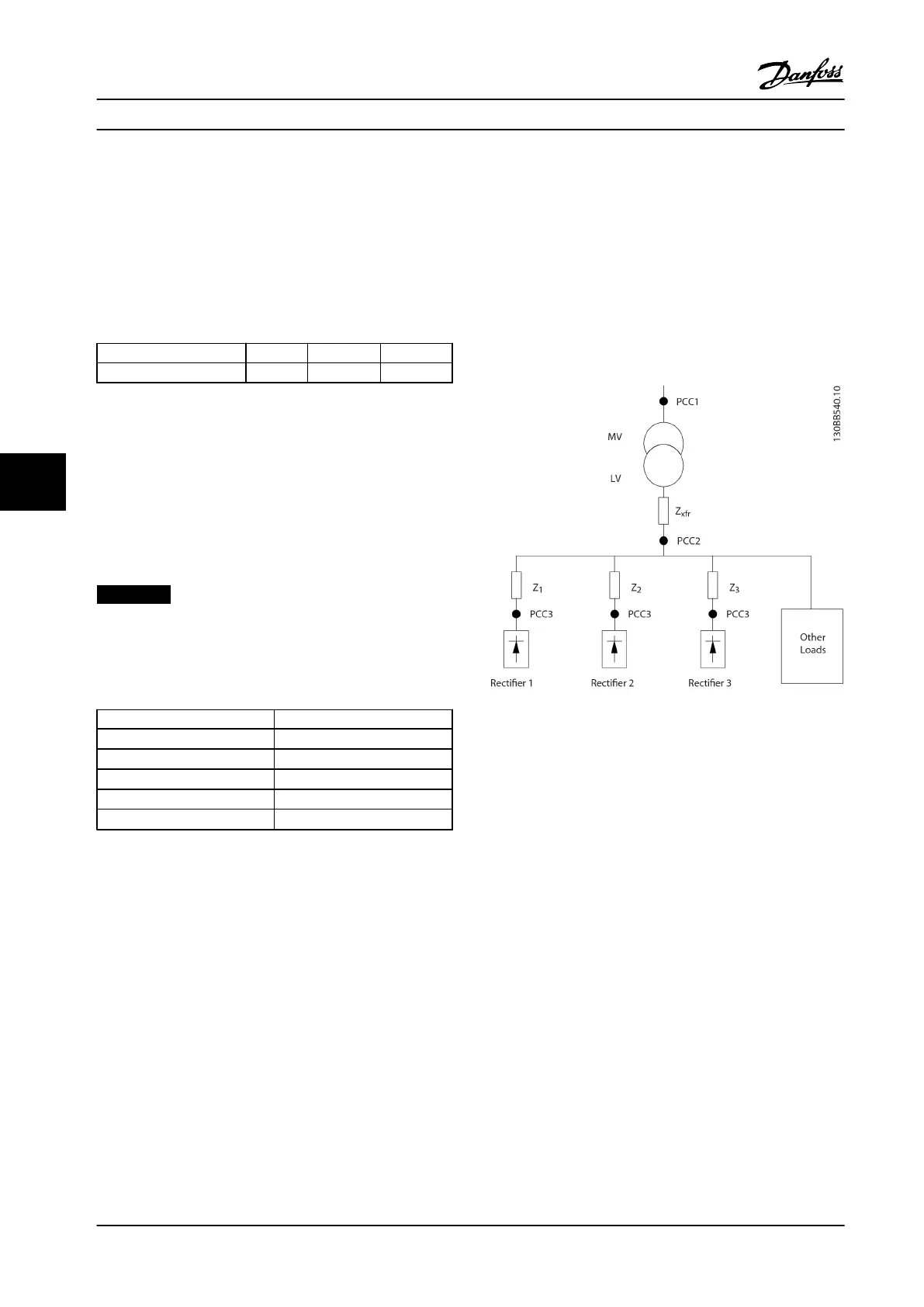
In Figure 7.63, a transformer is connected on the primary
side to a point of common coupling (PCC1) on the
medium voltage supply. The transformer has an
impedance of Z
xfr
and feeds a number of loads. The point
of common coupling where all loads are connected
together is PCC2. Each load is connected through cables
that have an impedance of Z
1
, Z
2
, Z
3
.
Figure 7.63 Small Distribution System
Harmonic currents drawn by non-linear loads cause
distortion of the voltage because of the voltage drop in
the impedances of the distribution system. Higher
impedances result in higher levels of voltage distortion.
Current distortion affects apparatus performance and the
individual load. Voltage distortion affects system
performance. It is not possible to determine the voltage
distortion in the PCC knowing only the load’s harmonic
performance. To predict the distortion in the PCC, the
configuration of the distribution system and relevant
impedances must be known.
Electrical Installation Design Guide
238 Danfoss A/S © Rev. 2014-02-10 All rights reserved. MG34S222
77

 Loading...


