3.4.10 Optimization of the process
regulator
After the basic settings have been made, optimize the
following:
•
Proportional gain
•
Integration time
•
Differentiation time
In most processes, this can be done by following these
steps:
1. Start the motor.
2.
Set 7-33 Process PID Proportional Gain to 0.3 and
increase it until the feedback signal begins to
vary continuously. Then, reduce the value until
the feedback signal has stabilized. Now lower the
proportional gain by 40–60%.
3.
Set 7-34 Process PID Integral Time to 20 s and
reduce the value until the feedback signal begins
to vary continuously. Increase the integration
time until the feedback signal stabilizes, followed
by an increase of 15%–50%.
4.
Only use 7-35 Process PID Differentiation Time for
very fast-acting systems only (differentiation
time). The typical value is four times the set
integration time. The differentiator should only be
used when the setting of the proportional gain
and the integration time has been fully
optimized. Make sure that oscillations on the
feedback signal are sufficiently dampened by the
low-pass filter on the feedback signal.
NOTICE!
If necessary, start/stop can be activated a number of
times to provoke a variation of the feedback signal.
3.4.11 Ziegler Nichols Tuning Method
Several tuning methods can be used to tune the PID
controls of the adjustable frequency drive. One approach is
to use the Ziegler Nichols tuning method.
NOTICE!
The method described must not be used on applications
that could be damaged by the oscillations created by
marginally stable control settings.
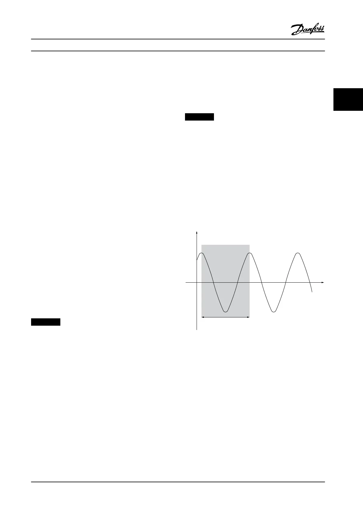
The criteria for adjusting the parameters are based on
evaluating the system at the limit of stability rather than
on taking a step response. The proportional gain is
increased until continuous oscillations are observed (as
measured on the feedback), that is, until the system
becomes marginally stable. The corresponding gain (K
u
) is
called the ultimate gain. The period of the oscillation (P
u
)
(called the ultimate period) is determined as shown in
Figure 3.25.
Figure 3.25 Marginally Stable System
Product Introduction Design Guide
MG34S222 Danfoss A/S © Rev. 2014-02-10 All rights reserved. 45
3 3

 Loading...


