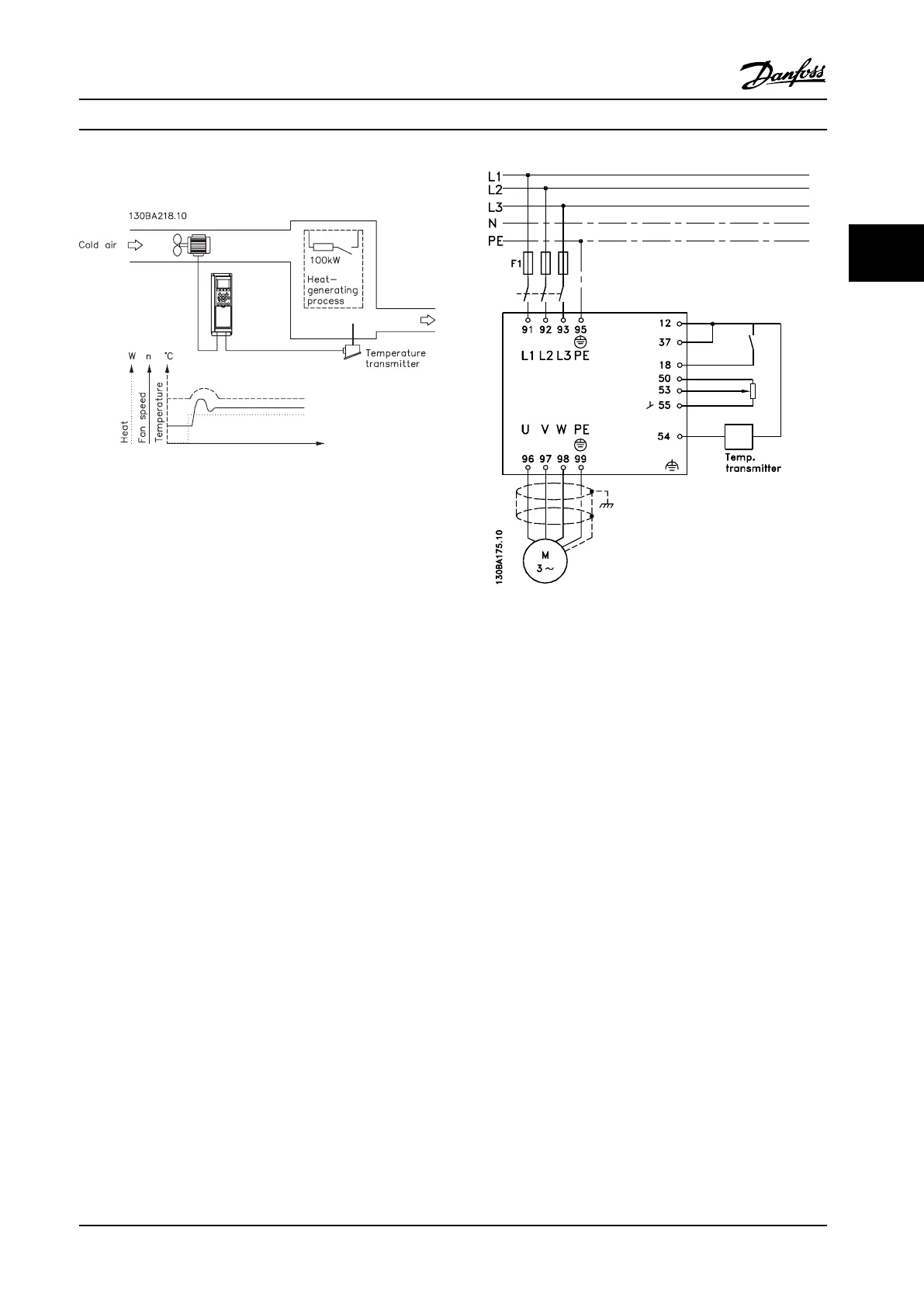
3.4.8 Example of Process PID Control
Figure 3.23 Example of a Process PID Control Used in a
Ventilation System
In this example using a ventilation system, the
temperature must be adjustable from 23–95 °F [-5–+35 °C]
with a potentiometer of 0–10 V. The process control is
used to keep the set temperature constant.
When the temperature increases, the process PID control
increases the ventilation speed so more airflow is
generated. When the temperature drops, the speed is
reduced. The transmitter used is a temperature sensor with
a working range of 14–104 °F [-10–+40 °C],
4–20 mA. Min./max. speed 300/1500 RPM.
Figure 3.24 Two-wire Transmitter
The following steps demonstrate how to set up the
Process PID Control in Figure 3.24.
1. Start/Stop via switch connected to terminal 18.
2. Temperature reference via potentiometer
(23–95 °F [-5–+35 °C], 0–10 V DC) connected to
terminal 53.
3. Temperature feedback via transmitter (14–104 °F
[-10–+40 °C], 4–20 mA) connected to terminal 54.
Switch S202 set to ON (current input).
Product Introduction Design Guide
MG34S222 Danfoss A/S © Rev. 2014-02-10 All rights reserved. 43
3 3

 Loading...


