3.4 PID Control
3.4.1 Speed PID Control
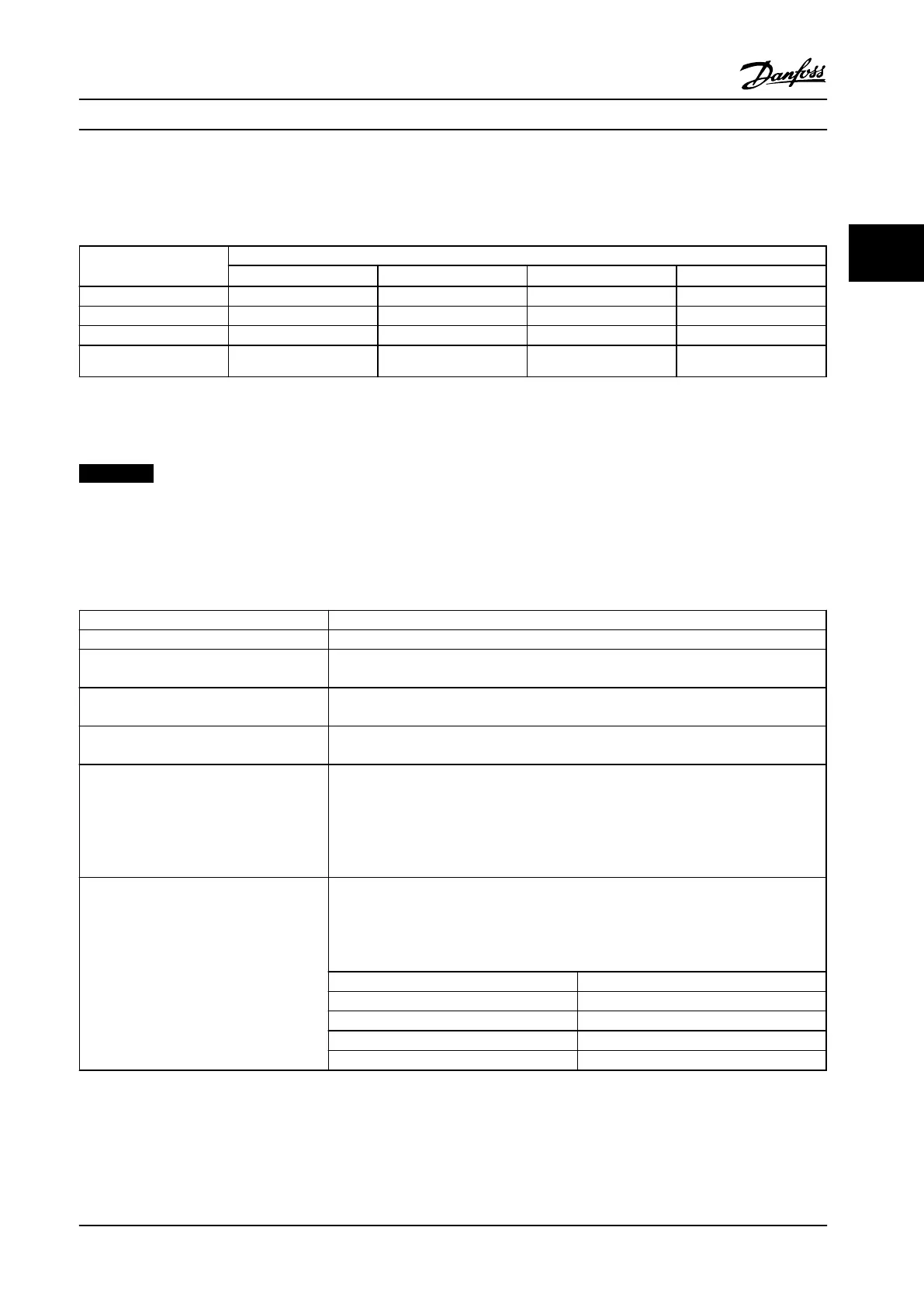
1-00 Configuration Mode 1-01 Motor Control Principle
U/f
VVC
plus
Flux sensorless Flux w/ enc. feedb
[0] Speed open-loop Not Active Not Active Active N.A.
[1] Speed closed-loop N.A. Active N.A. Active
[2] Torque N.A. N.A. N.A. Not Active
[3] Process Not Active Active Active
Table 3.6 Control Configurations Where the Speed Control is Active
“N.A.” means that the specific mode is not available. “Not Active” means that the specific mode is available but the Speed Control is not active in
that mode.
NOTICE!
The Speed Control PID works under the default parameter setting, but tuning the parameters is highly recommended to
optimize the motor control performance. The two flux motor control principles are particularly dependent on proper
tuning to yield their full potential.
3.4.2 Speed PID Control Parameters
Parameter Description of function
7-00 Speed PID Feedback Source Select from which input the speed PID should get its feedback.
30-83 Speed PID Proportional Gain The higher the value, the quicker the control. However, too high a value may lead to
oscillations.
7-03 Speed PID Integral Time Eliminates steady state speed error. Lower value means quick reaction. However, too low a
value may lead to oscillations.
7-04 Speed PID Differentiation Time Provides a gain proportional to the rate of feedback change. A setting of zero disables the
differentiator.
7-05 Speed PID Diff. Gain Limit If there are quick changes in reference or feedback in a given application - which means
that the error changes swiftly - the differentiator may soon become too dominant. This is
because it reacts to changes in the error. The quicker the error changes, the stronger the
differentiator gain is. The differentiator gain can thus be limited to allow setting of the
reasonable differentiation time for slow changes and a suitably quick gain for quick
changes.
7-06 Speed PID Lowpass Filter Time A low-pass filter dampens oscillations to the feedback signal and improves steady state
performance. However, too large a filter time will deteriorate the dynamic performance of
the speed PID control.
Practical settings of 7-06 Speed PID Lowpass Filter Time taken from the number of pulses
per revolution from encoder (PPR):
Encoder PPR 7-06 Speed PID Lowpass Filter Time
512 10 ms
1024 5 ms
2048 2 ms
4096 1 ms
Table 3.7 Relevant Parameters for the Speed PID Control
Product Introduction Design Guide
MG34S222 Danfoss A/S © Rev. 2014-02-10 All rights reserved. 37
3 3

 Loading...


