Figure 9.6 Rotation Direction
9.4 Resolver Option MCB 103
MCB 103 Resolver option is used for interfacing resolver
motor feedback to VLT
®
AutomationDrive. Resolvers are
used as motor feedback devices for permanent magnet
brushless synchronous motors.
When the resolver option is ordered separately, the kit
includes:
•
Resolver option MCB 103
•
Enlarged LCP fixture and enlarged terminal cover
Selection of parameters: 17-5* Resolver Interface.
MCB 103 Resolver Option supports a various number of
rotor resolver types.
Resolver Poles
17-50 Poles: 2 *2
Resolver Input
Voltage
17-51 Input Voltage: 2.0–8.0 Vrms *7.0 Vrms
Resolver Input
Frequency
17-52 Input Frequency: 2–15 kHz
*10.0 kHz
Transformation ratio
17-53 Transformation Ratio: 0.1–1.1 *0.5
Secondary input
voltage
Max 4 Vrms
Secondary load
App. 10 kΩ
Table 9.3 Resolver Specifications
Resolver Input
SW. ver. X.XX
MCB 103
Code No.
Option B
Rotor
Resolver
stator
Motor
LED 1 REF OK
LED 2 COS OK
LED 3 SIN OK
LED NA
130BA247.11
REF+
REF-
COS-
COS+
SIN+
SIN- S4
S2
S3
S1
R2
R1
COS-
COS+
REF+
REF-
SIN+
SIN-
A+
A-
B+
B-
Z+
Z-
X32/ 31 2 4 5 116 87 109 12
1 2 3 4
S1
S3
S4 S2
R1
R2
θ
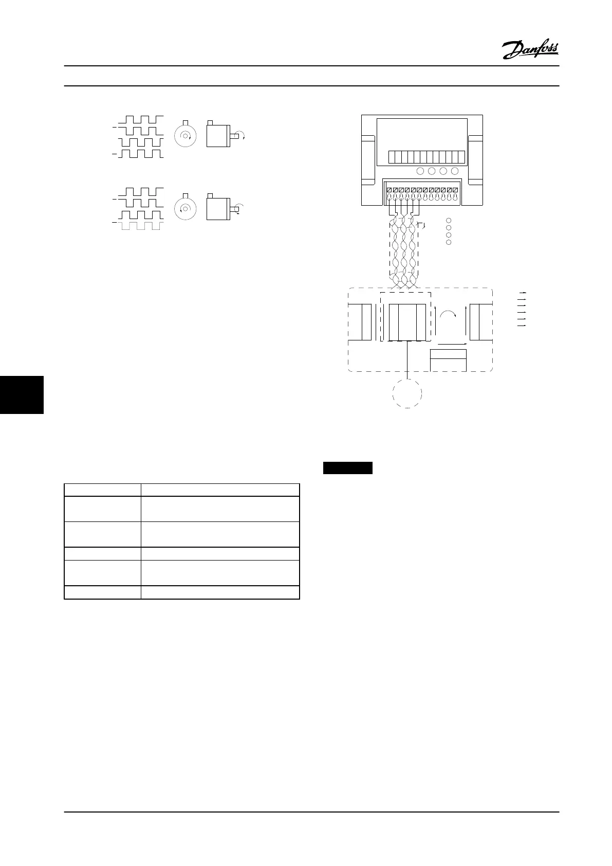
Figure 9.7 Resolver Option MCB 103 used with a Permanent
Magnet Motor
NOTICE!
The Resolver Option MCB 103 can be used with only
rotor-supplied resolver types. Stator-supplied resolvers
cannot be used.
LED Indicators
The LEDs are active when 17-61 Feedback Signal Monitoring
is set to Warning or Trip.
LED 1 is on when the reference signal is OK to resolver
LED 2 is on when cosine signal is OK from resolver
LED 3 is on when sinus signal is OK from resolver
Options and Accessories Design Guide
254 Danfoss A/S © Rev. 2014-02-10 All rights reserved. MG34S222
99

 Loading...


