Connector
designation
X31
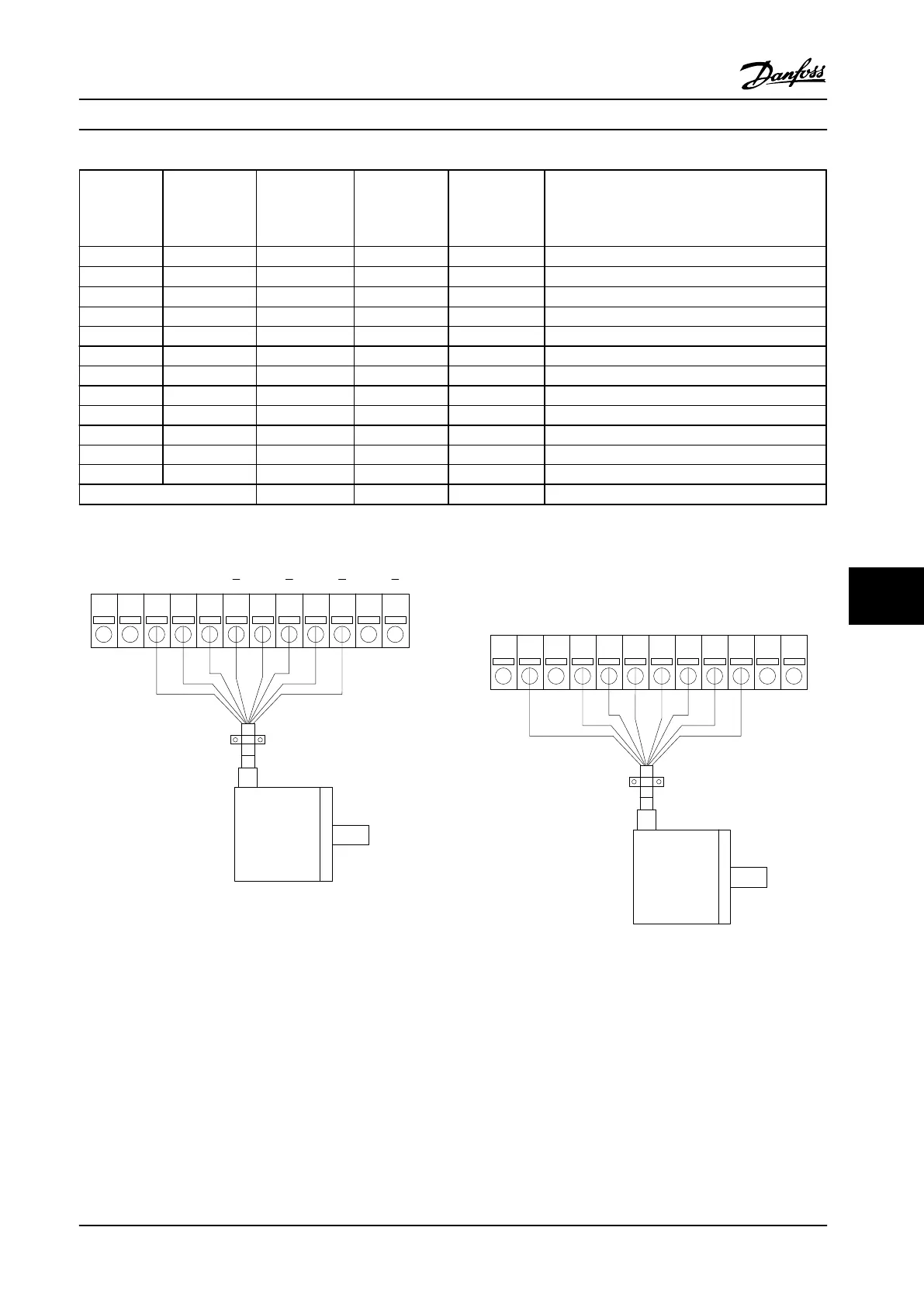
Incremental
encoder (refer
to Figure 9.4)
SinCos encoder
Hiperface
®
(refer to
Figure 9.5)
EnDat encoder SSI encoder Description
1 NC 24 V* 24 V Output (21–25 V, I
max
125 mA)
2 NC 8 Vcc 8 V output (7–12 V, I
max
: 200 mA)
3 5 VCC 5 VCC 5 V* 5 V Output (5 V ±5%, I
max
: 200 mA)
4 GND GND GND GND
5 A input +COS +COS A input
6 A inv input REFCOS REFCOS A inv input
7 B input +SIN +SIN B input
8 B inv input REFSIN REFSIN B inv input
9 Z input +Data RS-485 Clock out Clock out Z input OR +Data RS-485
10 Z inv input -Data RS-485 Clock out inv. Clock out inv. Z input OR -Data RS-485
11 NC NC Data in Data in Future use
12 NC NC Data in inv. Data in inv. Future use
Max. 5 V on X31.5-12
Table 9.2 Encoder Option MCB 102 Terminal Descriptions for Supported Encoder Types
* Supply for encoder: see data on encoder
1
2 3 12
130BA163.11
754 6 8 9 10 11
24 V
8 V 5 V GND A A B B Z Z D D
Figure 9.4 Incremental Encoder
Max. cable length 492 ft [150 m].
Us 7-12V (red)
GND (blue)
+COS (pink)
REFCOS (black)
+SIN (white)
REFSIN (brown)
Data +RS 485 (gray)
Data -RS 485 (green)
1 2 3 12754 6 8 9 10 11
130BA164.10
Figure 9.5 SinCos Encoder Hiperface
Options and Accessories Design Guide
MG34S222 Danfoss A/S © Rev. 2014-02-10 All rights reserved. 253
9 9

 Loading...


