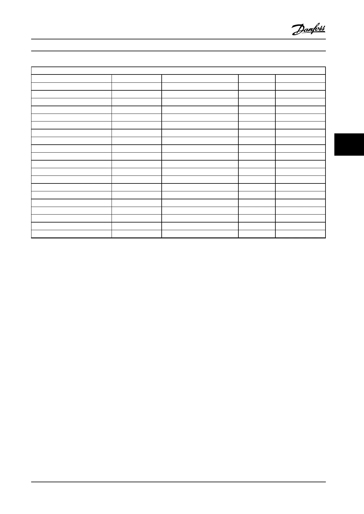
525–690 V AC
FC 302 [T7] Pm (HO) (hp [kW])
Number of brake choppers
(1)
R
min
R
br,nom
N55K 75 [55] 1 13.5 11.0
N75K 100 [75] 1 8.8 9.4
N90K 125 [90] 1 8.2 7.5
N110 150 [110] 1 6.6 6.2
N132 175 [132] 1 4.2 5.2
N160 225 [160] 1 4.2 4.2
N200 275 [200] 1 3.4 3.3
N250 350 [250] 1 2.3 2.8
N315 425 [315] 1 2.3 2.4
P355 475 [355] 1 2.3 2.4
P400 550 [400] 1 2.1 2.1
P500 650 [500] 1 2.0 2.0
P560 750 [560] 1 2.0 2.0
P630 850 [630] 2 1.3 1.3
P710 950 [710] 2 1.1 1.2
P800 1075 [800] 2 1.1 1.1
P900 1200 [900] 3 1.0 1.0
P1M0 1350 [1000] 3 0.8 0.84
P1M2 1600 [1200] 3 0.7 0.70
P1M4 1875 [1400] 4 0.55 0.60
Table 5.10 Brake Chopper Data 525–690 V
R
min
=Minimum brake resistance that can be used with this adjustable frequency drive. If the adjustable frequency drive includes multiple brake
choppers, the resistance value is the sum of all resisters in parallel.
R
br,nom
=Nominal resistance required to achieve 150% braking torque.
R
rec
=Resistance value of the recommended Danfoss brake resistor.
1)
Larger adjustable frequency drives include multiple inverter modules with a brake chopper in each inverter. Equal resistors should be connected
to each brake chopper.
How to Order Design Guide
MG34S222 Danfoss A/S © Rev. 2014-02-10 All rights reserved. 97
5 5

 Loading...


