D-frame Cooling Fans
All adjustable frequency drives in this size range are
equipped with cooling fans to provide airflow along the
heatsink. Units in IP21 (NEMA 1) and IP54 (NEMA 12)
enclosures have a fan mounted in the enclosure door to
provide more airflow to the unit. IP20 enclosures have a
fan mounted to the top of the unit for more cooling. There
is a small 24 V DC mixing fan mounted under the input
plate. This fan operates any time the adjustable frequency
drive is powered on.
DC voltage from the power card powers the fans. The
mixing fan is powered by 24 V DC from the main switch
mode power supply. The heatsink fan and the door/top
fan are powered by 48 V DC from a dedicated switch
mode power supply on the power card. Each fan has
tachometer feedback to the control card to confirm that
the fan is operating correctly. On/off and speed control of
the fans is provided to reduce overall acoustical noise and
extend the life of the fans.
The following conditions activate fans on the D-frame:
•
Output current greater than 60% of nominal
•
IGBT over-temperature
•
IGBT low temperature
•
Control card over temperature
•
DC hold active
•
DC brake active
•
Dynamic brake circuit active
•
During pre-magnetization of the motor
•
AMA in progress
In addition to these conditions, the fans are always started
shortly after line input power is applied to the adjustable
frequency drive. Once fans are started, they run for a
minimum of one minute.
The following conditions activate fans on the E- and F-
frames:
1. AMA
2. DC Hold
3. Pre-Mag
4. DC Brake
5. 60% of nominal current is exceeded
6. Specific heatsink temperature exceeded (power
size dependent)
7. Specific power card ambient temperature
exceeded (power-size dependent)
8. Specific control card ambient temperature
exceeded
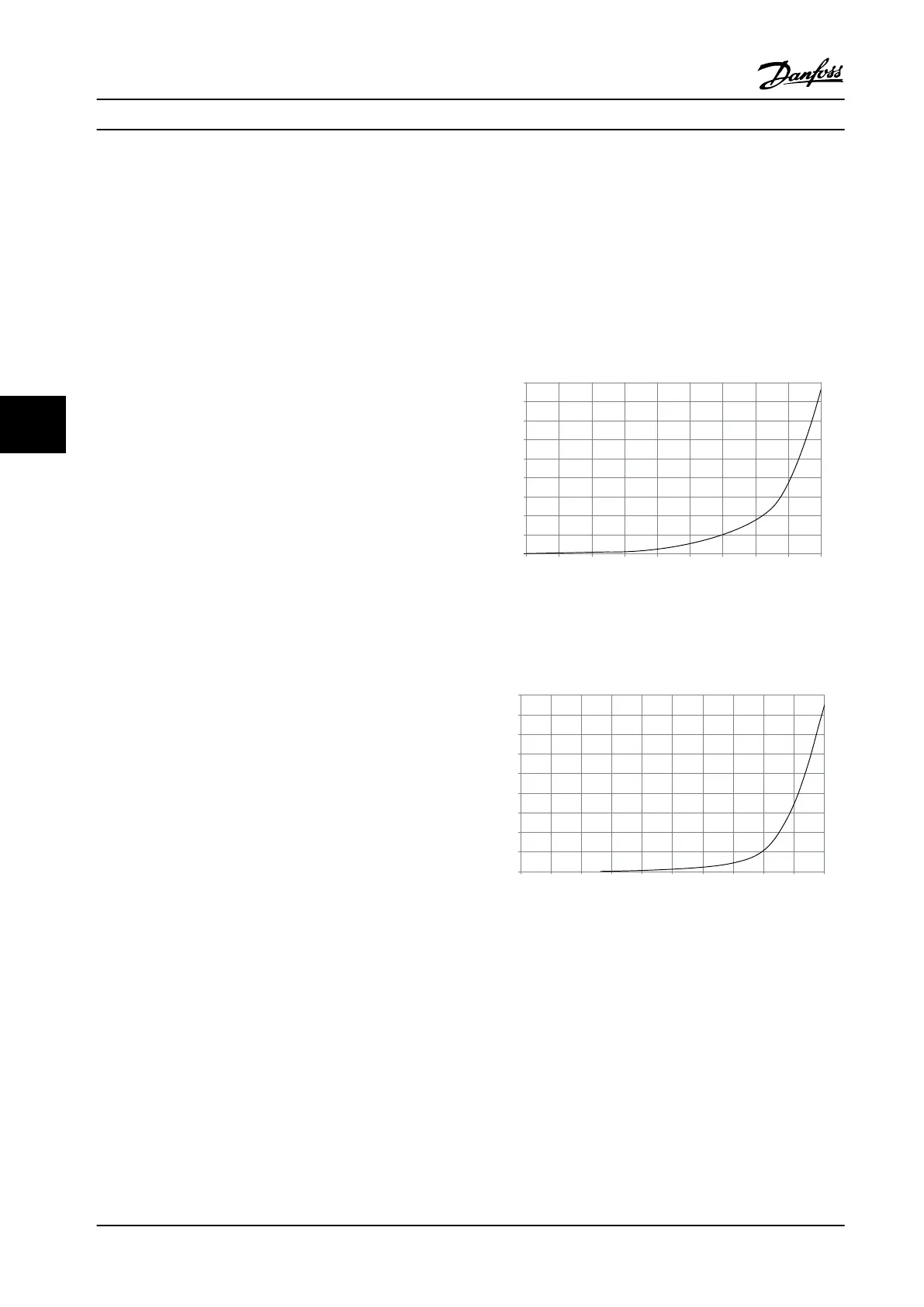
External Ducts
If more duct work is added externally to the Rittal cabinet,
the pressure drop in the ducting must be calculated. Use
the derating charts to derate the adjustable frequency
drive according to the pressure drop.
90
80
70
60
50
40
30
20
10
0
0 0.5 4.9 13 27.3 45.9 66 89.3 115.7 147
(%)
(Pa)
Pressure Increase
Drive Derating
130BB007.10
Figure 6.95 D-frame Derating vs. Pressure Change. Adjustable
Frequency Drive Airflow: 450 cfm (765 m
3
/h)
90
80
70
60
50
40
30
20
10
0
(%)
Drive Derating
0 0 0.1 3.6 9.8 21.5 43.4 76 237.5 278.9
(Pa)
Pressure Change
130BB010.10
147.1
Figure 6.96 E-frame Derating vs. Pressure Change (Small Fan),
P250T5 and P355T7-P400T7. Adjustable Frequency Drive
Airflow: 650 cfm (1,105 m
3
/h)
Mechanical Installation Design Guide
174 Danfoss A/S © Rev. 2014-02-10 All rights reserved. MG34S222
66

 Loading...


