EasyManuals Logo
Home>Danfoss>DC Drives>VLT AutomationDrive FC 300

Danfoss VLT AutomationDrive FC 300 Design Guide

Danfoss VLT AutomationDrive FC 300
296 pages
To Next Page IconTo Next Page
To Previous Page IconTo Previous Page
Page #229 background imageLoading...
Page #229 background image
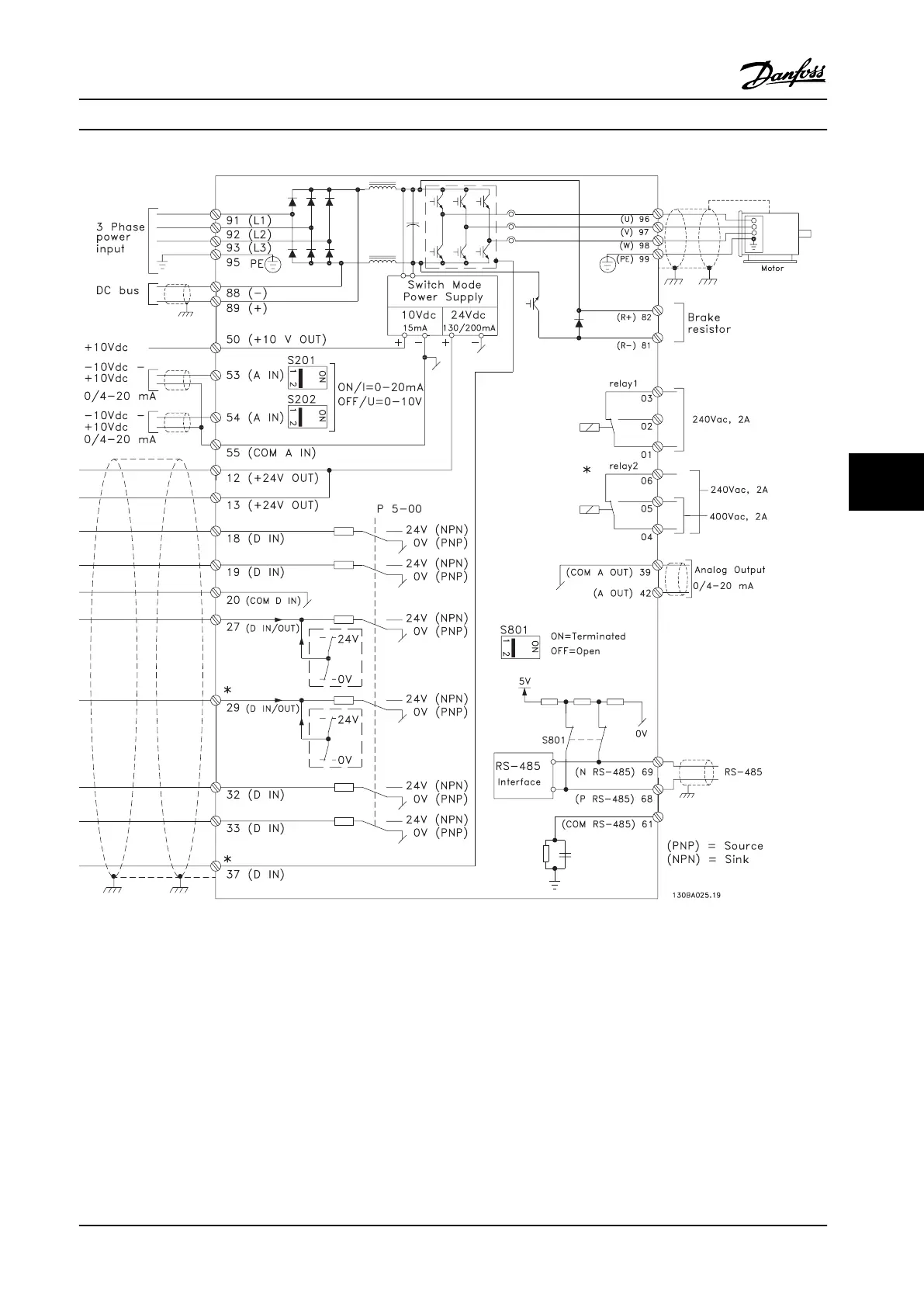
Figure 7.44 Interconnect Diagram, E- and F-Frame Adjustable Frequency Drives
Very long control cables and analog signals may result in 50/60 Hz ground loops due to noise from line power supply
cables. If this occurs, it may be necessary to break the shield or insert a 100 nF capacitor between shield and chassis.
Connect the digital and analog inputs and outputs separately to the common inputs (terminal 20, 55, 39) of the adjustable
frequency drive to avoid ground currents from both groups affecting other groups. For example, switching on the digital
input may disturb the analog input signal.
Electrical Installation
Design Guide
MG34S222 Danfoss A/S © Rev. 2014-02-10 All rights reserved. 227
7 7

Table of Contents

Other manuals for Danfoss VLT AutomationDrive FC 300

Questions and Answers:

Question and Answer IconNeed help?

Do you have a question about the Danfoss VLT AutomationDrive FC 300 and is the answer not in the manual?

Danfoss VLT AutomationDrive FC 300 Specifications

General IconGeneral
BrandDanfoss
ModelVLT AutomationDrive FC 300
CategoryDC Drives
LanguageEnglish

Related product manuals