10.13.4 Control Word According to
PROFIdrive Profile (CTW)
The control word is used to send commands from a master
(e.g., a PC) to a follower.
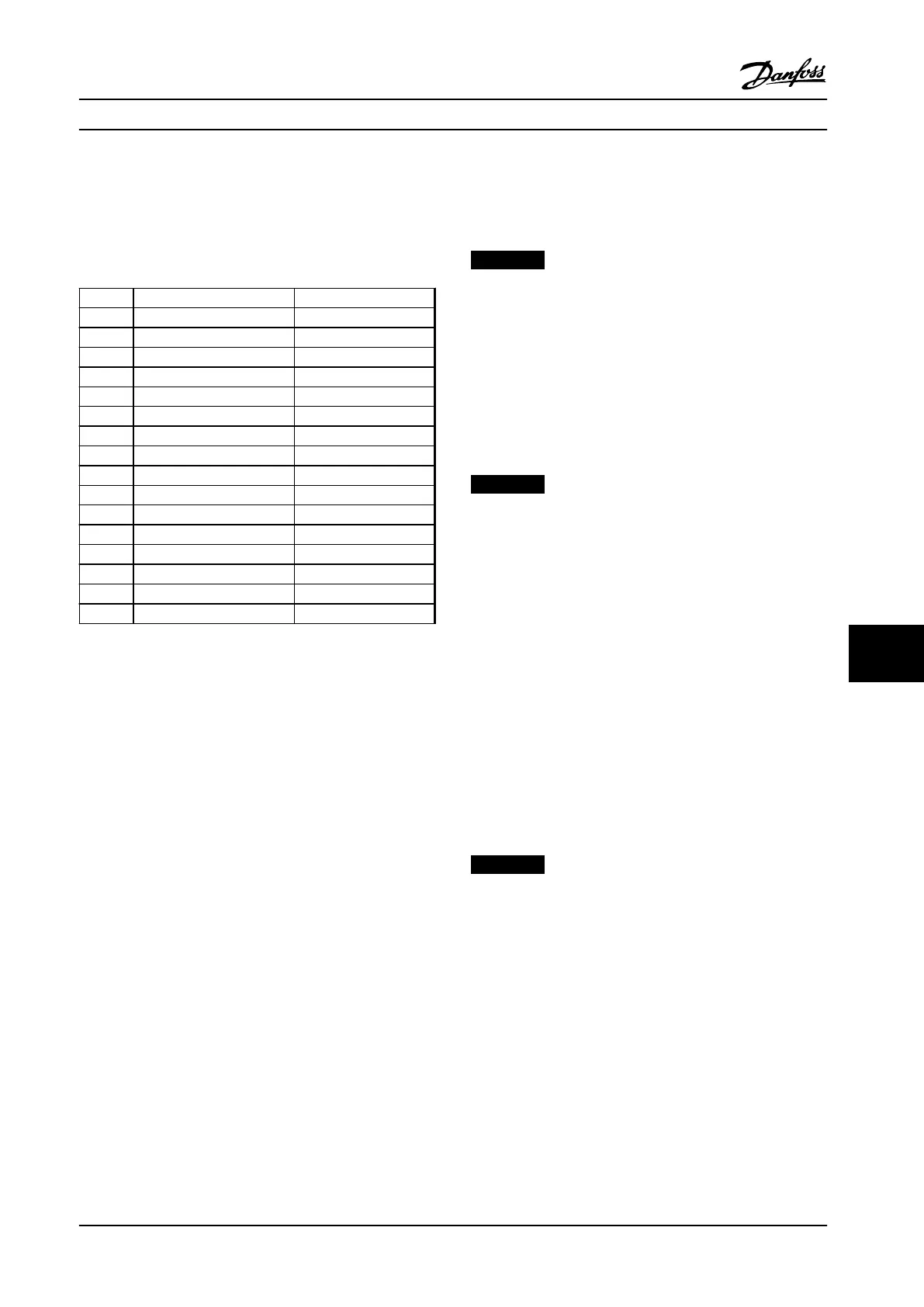
Bit Bit=0 Bit=1
00 OFF 1 ON 1
01 OFF 2 ON 2
02 OFF 3 ON 3
03 Coasting No coasting
04 Quick stop Ramp
05 Hold frequency output Use ramp
06 Ramp stop Start
07 No function Reset
08 Jog 1 OFF Jog 1 ON
09 Jog 2 OFF Jog 2 ON
10 Data invalid Data valid
11 No function Slow-down
12 No function Catch up
13 Parameter set-up Selection lsb
14 Parameter set-up Selection msb
15 No function Reverse
Table 10.21 Bit Values for Control Word, PROFIdrive Profile
Explanation of the control bits
Bit 00, OFF 1/ON 1
Normal ramp stops using the ramp times of the actual
selected ramp.
Bit 00="0" leads to the stop and activation of the output
relay 1 or 2 if the output frequency is 0 Hz and if [Relay
123] has been selected in 5-40 Function Relay.
When bit 00="1", the adjustable frequency drive is in State
1: “Switching on inhibited”.
Bit 01, OFF 2/ON 2
Coasting stop
When bit 01="0", a coasting stop and activation of the
output relay 1 or 2 occurs if the output frequency is 0 Hz
and if [Relay 123] has been selected in 5-40 Function Relay.
When bit 01="1", the adjustable frequency drive is in State
1: “Switching on inhibited”. Refer to Table 10.22, at the end
of this section.
Bit 02, OFF 3/ON 3
Quick stop using the ramp time of 3-81 Quick Stop Ramp
Time.
When bit 02="0", a quick stop and activation of the output
relay 1 or 2 occurs if the output frequency is 0 Hz and if
[Relay 123] has been selected in 5-40 Function Relay.
When bit 02="1", the adjustable frequency drive is in State
1: “Switching on inhibited”.
Bit 03, Coasting/No coasting
Coasting stop Bit 03="0" leads to a stop.
When bit 03="1", the adjustable frequency drive can start if
the other start conditions are satisfied.
NOTICE!
The selection in 8-50 Coasting Select determines how bit
03 is linked with the corresponding function of the
digital inputs.
Bit 04, Quick stop/Ramp
Quick stop using the ramp time of 3-81 Quick Stop Ramp
Time.
When bit 04="0", a quick stop occurs.
When bit 04="1", the adjustable frequency drive can start if
the other start conditions are satisfied.
NOTICE!
The selection in 8-51 Quick Stop Select determines how
bit 04 is linked with the corresponding function of the
digital inputs.
Bit 05, Hold frequency output/Use ramp
When bit 05="0", the current output frequency is being
maintained even if the reference value is modified.
When bit 05="1", the adjustable frequency drive can
perform its regulating function again; operation occurs
according to the respective reference value.
Bit 06, Ramp stop/Start
Normal ramp stop using the ramp times of the actual
ramp as selected. In addition, activation of the output relay
01 or 04 if the output frequency is 0 Hz if Relay 123 has
been selected in 5-40 Function Relay.
Bit 06="0" leads to a stop.
When bit 06="1", the adjustable frequency drive can start if
the other start conditions are satisfied.
NOTICE!
The selection in 8-53 Start Select determines how bit 06
is linked with the corresponding function of the digital
inputs.
Bit 07, No function/Reset
Reset after switching off.
Acknowledges event in fault buffer.
When bit 07="0", no reset occurs.
When there is a slope change of bit 07 to "1", a reset
occurs after switching off.
Bit 08, Jog 1 OFF/ON
Activates the pre-programmed speed in 8-90 Bus Jog 1
Speed. JOG 1 is only possible if bit 04="0" and bit
00-03="1".
RS-485 Installation and Set...
Design Guide
MG34S222 Danfoss A/S © Rev. 2014-02-10 All rights reserved. 285
10 10

 Loading...


