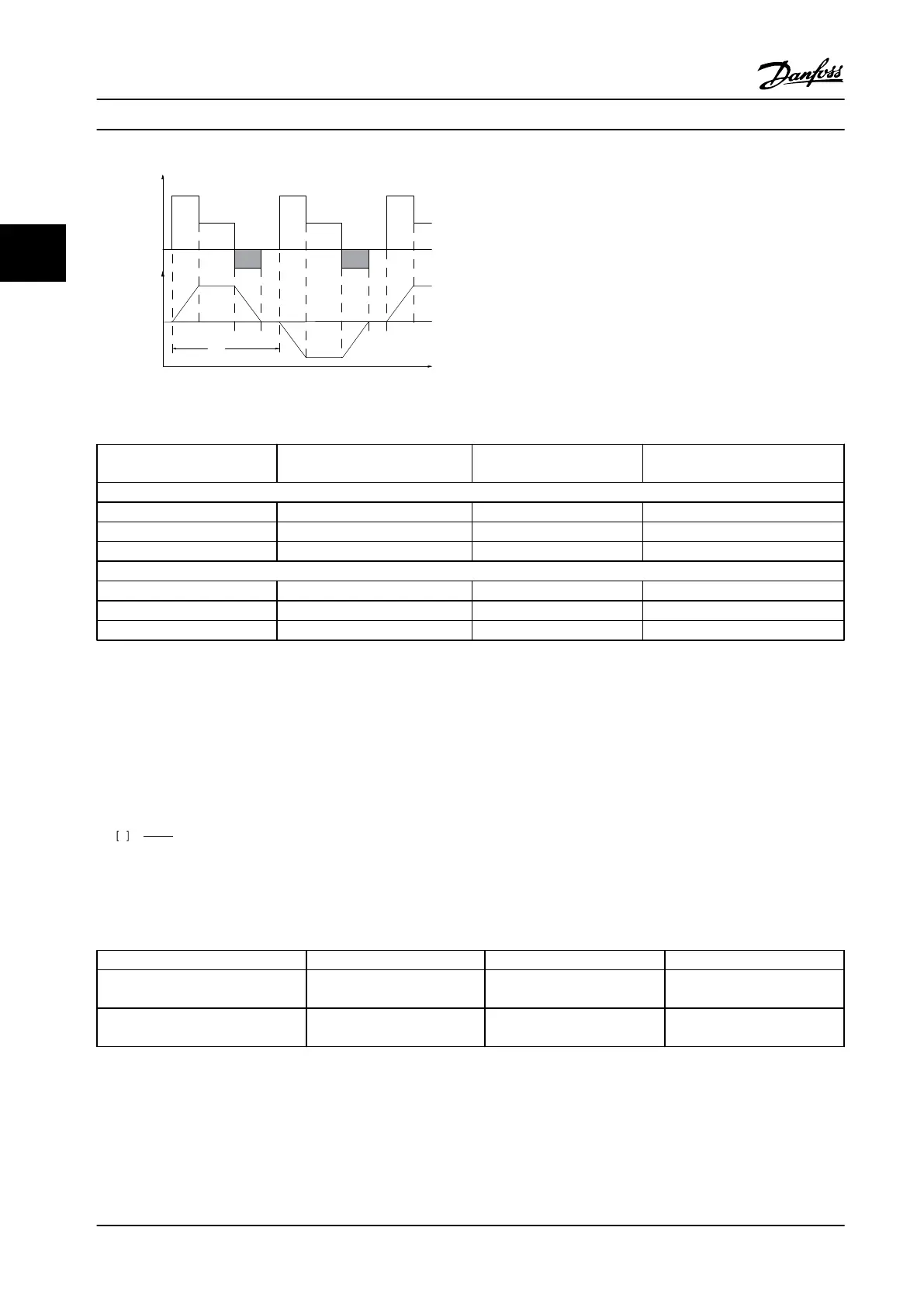
T
ta
tc
tb
to ta
tc
tb
to ta
130BA167.10
Load
Time
Speed
Figure 3.32 Typical Braking Cycle
Cycle time (s)
Braking duty cycle at 100%
torque
Braking duty cycle at over torque
(150/160%)
380–500 V
N90K-N160 600 Continuous 10%
N200-N250 600 Continuous 10%
P315-P800 600 40% 10%
525–690 V
N55K-N315, P355-P400 600 40% 10%
P500-P560 600 40% 10%
P630-P1M0 600 40% 10%
Table 3.18 Braking at High Overload Torque Level
Danfoss offers brake resistors with duty cycle of 5%, 10% and 40%. If a 10% duty cycle is applied, the brake resistors are
able to absorb braking energy for 10% of the cycle time. The remaining 90% of the cycle time is used on dissipating excess
heat.
Make sure the resistor is designed to handle the required braking time. The maximum permissible load on the brake resistor
is stated as a peak power at a given intermittent duty cycle. The brake resistance is calculated as shown:
R
br
Ω =
U
dc
2
P
peak
where
P
peak
=P
motor
xM
br
[%]xη
motor
xη
VLT
[W]
As can be seen, the brake resistance depends on the intermediate circuit voltage (U
dc
).
Size Brake active Warning before cut-out Cut-out (trip)
FC 302
3x380–500 V*
810 V/795 V 84 V/828 V 850 V/855 V
FC 302
3x525–690 V
1084 V 1109 V 1130 V
Table 3.19 Brake Limits
* Power size dependent
Product Introduction Design Guide
54 Danfoss A/S © Rev. 2014-02-10 All rights reserved. MG34S222
33

 Loading...


