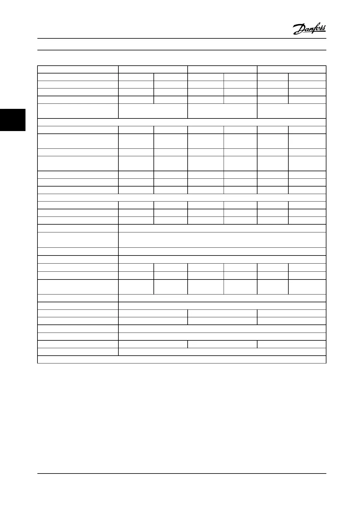
FC 302 P630 P710 P800
High/Normal load HO NO HO NO HO NO
Typical shaft output at 550 V [kW] 500 560 560 670 670 750
Typical shaft output at 575 V [HP] 650 750 750 950 950 1050
Typical shaft output at 690 V [kW] 630 710 710 800 800 900
Enclosure IP21, IP54 without/with
options cabinet
F10/F11 F10/F11 F10/F11
Output current
Continuous (at 550 V) [A] 659 763 763 889 889 988
Intermittent (60 s overload) (at 550 V)
[A]
989 839 1145 978 1334 1087
Continuous (at 575/690 V) [A] 630 730 730 850 850 945
Intermittent (60 s overload) (at
575/690 V) [A]
945 803 1095 935 1275 1040
Continuous KVA (at 550 V) [KVA] 628 727 727 847 847 941
Continuous KVA (at 575 V) [KVA] 627 727 727 847 847 941
Continuous KVA (at 690 V) [KVA] 753 872 872 1016 1016 1129
Maximum input current
Continuous (at 550 V) [A] 642 743 743 866 866 962
Continuous (at 575 V) [A] 613 711 711 828 828 920
Continuous (at 690 V) [A] 613 711 711 828 828 920
Max. cable size, motor [mm
2
(AWG)
1)
]
8x150 (8x300 mcm)
Max. cable size, line power
[mm
2
(AWG)
1)
]
6x120 (6x250 mcm)
Max. cable size, brake [mm
2
(AWG)
1)
]
4x185 (4x350 mcm)
Max. external electrical fuses [A]
2)
900
Estimated power loss at 600 V [W]
3)
4)
8075 9500 9165 10872 10860 12316
Estimated power loss at 690 V [W]
3)
4)
8388 9863 9537 11304 11291 12798
F3/F4 Max added losses CB or
disconnect & contactor
342 427 419 532 519 615
Max panel options losses 400
Weight, enclosure IP21, IP54 [kg] 1017/1319
Weight, rectifier module [kg] 102 102 102
Weight, inverter module [kg] 102 102 136
Efficiency
4)
0.98
Output frequency 0–500 Hz
Power heatsink overtemp. trip 203 °F [95 °C] 221 °F [105 °C] 203 °F [95 °C]
Power card ambient trip 185 °F [85 °C]
* High overload=160% torque during 60 s, Normal overload=110% torque during 60 s
Table 4.13 Technical Specifications, F10/F11 frames, 525–690 V Line Power Supply 6x525–690 V AC, 12-Pulse
1) American Wire Gauge.
2) For fuse ratings, see chapter 7.2.1 Fuses.
3) Typical power loss is at normal conditions and expected to be within
±
15% (tolerance relates to variety in voltage and cable conditions.) These
values are based on a typical motor efficiency (IE/IE3 border line). Lower efficiency motors add to the power loss in the adjustable frequency drive.
If the switching frequency is raised from nominal, the power losses rise significantly. LCP and typical control card power consumptions are
included. Options and customer load can add up to 30 W to the losses, though usually a fully loaded control card and options for slots A and B
each add only 4 W.
4) Measured using 16.5 ft. [5 m] shielded motor cables at rated load and rated frequency.
Selection
Design Guide
76 Danfoss A/S © Rev. 2014-02-10 All rights reserved. MG34S222
44

 Loading...


