Analog Inputs
Number of analog inputs 2
Terminal number 53, 54
Modes Voltage or current
Mode select Switch A53 and A54 (D-Frame) S201 and S202 (E & F-Frames)
Voltage mode Switch A53 and A54 (D-Frame) S201 and S202 (E & F-Frames)=OFF (U)
Voltage level -10 to +10 V (scaleable)
Input resistance, R
i
approx. 10 kΩ
Max. voltage ± 20 V
Current mode Switch A53 and A54 (D-Frame) S201 and S202 (E & F-Frames)=ON (I)
Current level 0/4 to 20 mA (scaleable)
Input resistance, R
i
approx. 200 Ω
Max. current 30 mA
Resolution for analog inputs 10 bit (+sign)
Accuracy of analog inputs Max. error 0.5% of full scale
Bandwidth 100 Hz
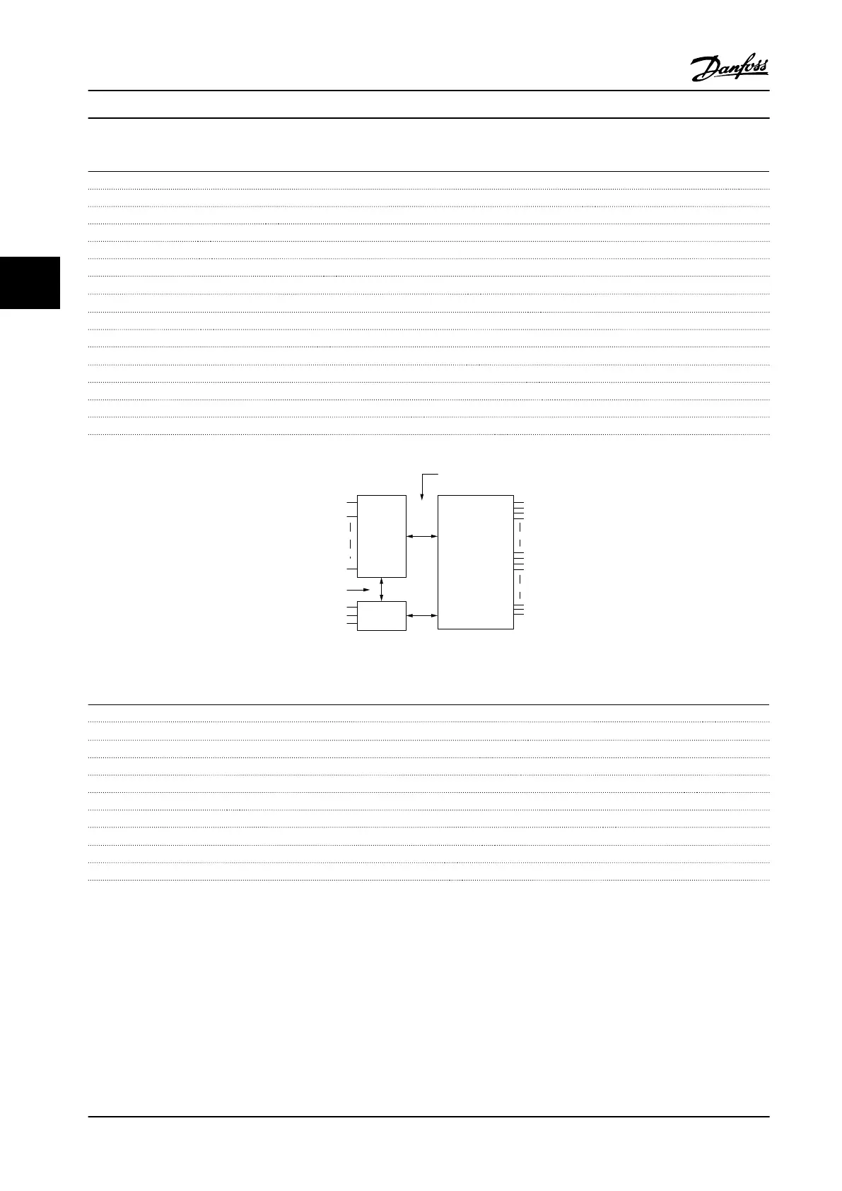
The analog inputs are galvanically isolated from the supply voltage (PELV) and other high-voltage terminals.
Mains
Functional
isolation
PELV isolation
Motor
DC-Bus
High
voltage
Control
+24V
RS485
18
37
130BA117.10
Figure 4.1 PELV Isolation
Pulse/Encoder Inputs
Programmable pulse/encoder inputs 2/1
Terminal number pulse/encoder 29
1)
, 33
2)
/32
3)
, 33
3)
Max. frequency at terminal 29, 32, 33 110 kHz (push-pull driven)
Max. frequency at terminal 29, 32, 33 5 kHz (open collector)
Min. frequency at terminal 29, 32, 33 4 Hz
Voltage level see chapter 9.2.2 Digital Inputs - Terminal X30/1-4
Maximum voltage on input 28 V DC
Input resistance, R
i
approx. 4 kΩ
Pulse input accuracy (0.1–1 kHz) Max. error: 0.1% of full scale
Encoder input accuracy (1–11 kHz) Max. error: 0.05% of full scale
The pulse and encoder inputs (terminals 29, 32, 33) are galvanically isolated from the supply voltage (PELV) and other high-
voltage terminals.
1)
FC 302 only
2)
Pulse inputs are 29 and 33
3)
Encoder inputs: 32=A, and 33=B
Selection
Design Guide
80 Danfoss A/S © Rev. 2014-02-10 All rights reserved. MG34S222
44

 Loading...


