Indicator, Button
Or Connector
and system board. Lights amber
when the system needs attention
due to a problem.
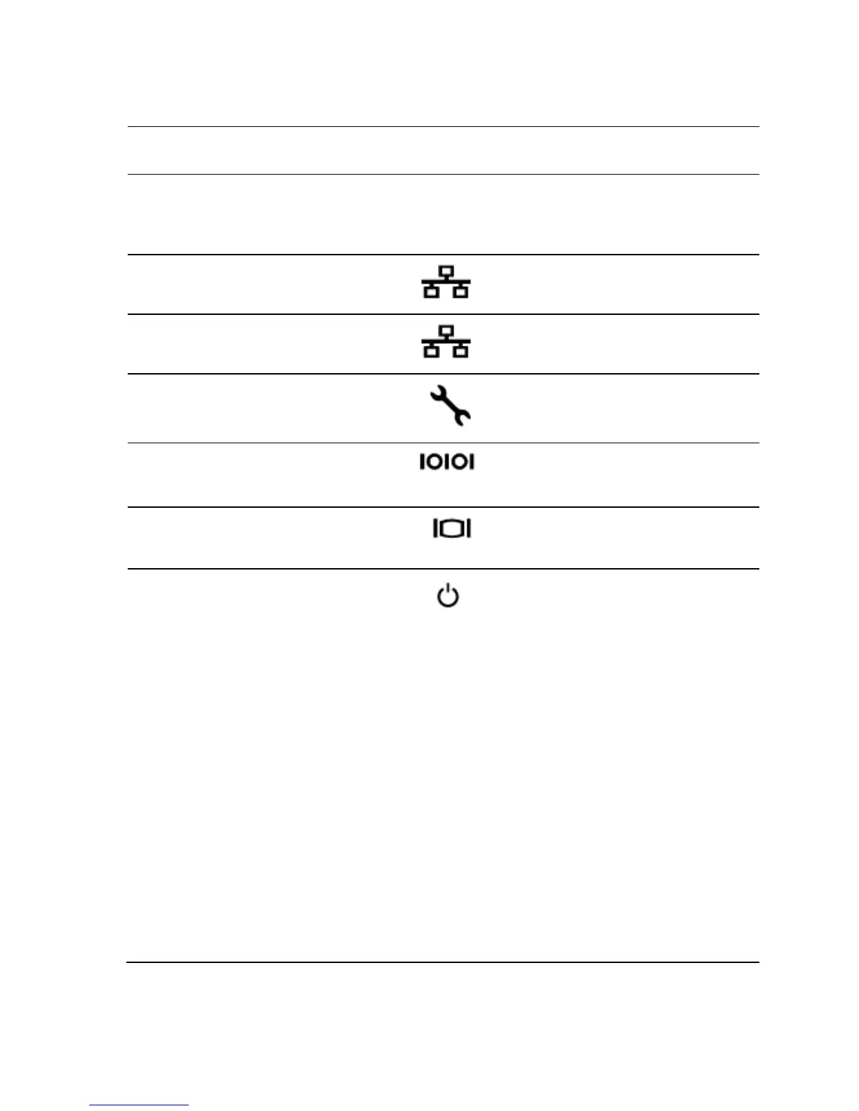
Dedicated management port.
Connects a serial device to the
Connects a VGA display to the
system state indicator/
power button
The power-on indicator turns to
green when the system power is
on.
The power-on indicator turns to
amber when the system critical
event occurs.
The power button controls the
DC power supply output to the
system.
When powering on the
system, the video monitor can take
from several seconds to over 2
minutes to display an image,
depending on the amount of
memory installed in the system.
operating systems, turning off the

 Loading...