5
Jumpers and Connectors | 321
Jumpers and Connectors
This chapter provides specific information about the system jumpers. It
also provides some basic information on jumpers and switches and
describes the connectors on the various boards in the system.
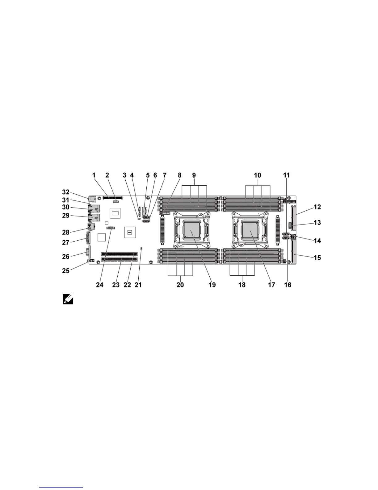
C6220 II System Board Connectors
Figure 5-1. C6220 II System Board Connectors
NOTE: The internal USB connector is used for riser SD interface.
PCI-E Gen3 x8 mezzanine slot 3
onboard SATA output connector 0
DIMM slots for processor 1
DIMM slots for processor 2
SAS/SATA input connector 5
SAS/SATA input connector 0
SAS/SATA input connector 4
DIMM slots for processor 2

 Loading...