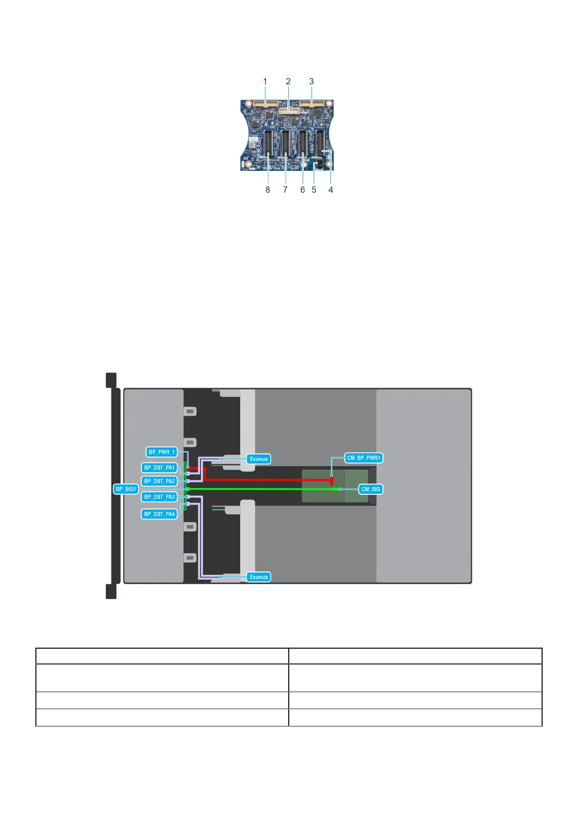
Figure 89. 8 x E3.s SSD backplane
1. Test connector
2. Backplane signal cable
3. Test connector
4. Backplane signal cable to sled 1
5. Backplane power connector
6. Backplane signal cable to sled 2
7. Backplane signal cable to sled 3
8. Backplane signal cable to sled 4
Backplane cable routing
Figure 90. Cabling the 8 x E3.s backplane with E3.s drives
Table 12. Cabling the 8 x E3.s backplane with E3.s drives
From To
Examax (Examax connector) BP_DST_PA1, BP_DST_PA2 (backplane signal connector 1
and 2)
CM_BP_PWR1 (chassis manager board power connector) BP_PWR_1 (backplane power connector)
CM_SIG (chassis manager board signal connector) BP_SIG1 (backplane signal connector)
Installing and removing system components 85