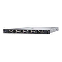
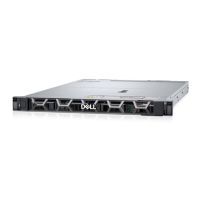
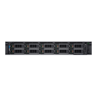
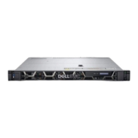
Figure 55. Configuration 27: Dell DPU (Mellanox: 25 Gb, Pensando: 100 Gb or 25 Gb) without power cable
NOTE: Follow the sequential order as shown in the table to remove the cables, to install the cables follow the reverse
sequential order.
Table 97. Dell DPU (Mellanox: 25 Gb, Pensando: 100 Gb or 25 Gb) without power cable
Order From To
1 J_REAR_SERIAL1 ( UART connector on rear I/O
card)
UART (UART connector on MIC card)
2 CON1 (Connector 1 on MIC card) Connector on DPU card in riser 1
Optional front bezel
NOTE: LCD panel is optional on the front bezel. If the front bezel has an LCD panel, see LCD panel section.
Removing the front bezel
The procedure to remove the front bezel with and without the LCD panel is the same.
Prerequisites
1. Follow the safety guidelines listed in the Safety instructions.
2. Keep the bezel key handy.
NOTE: The bezel key is part of the LCD bezel package.
Steps
1. Unlock the bezel.
2. Press the release button, and disengage the left end of the bezel.
3. Unhook the right end, and remove the bezel.
100
Installing and removing system components

 Loading...


