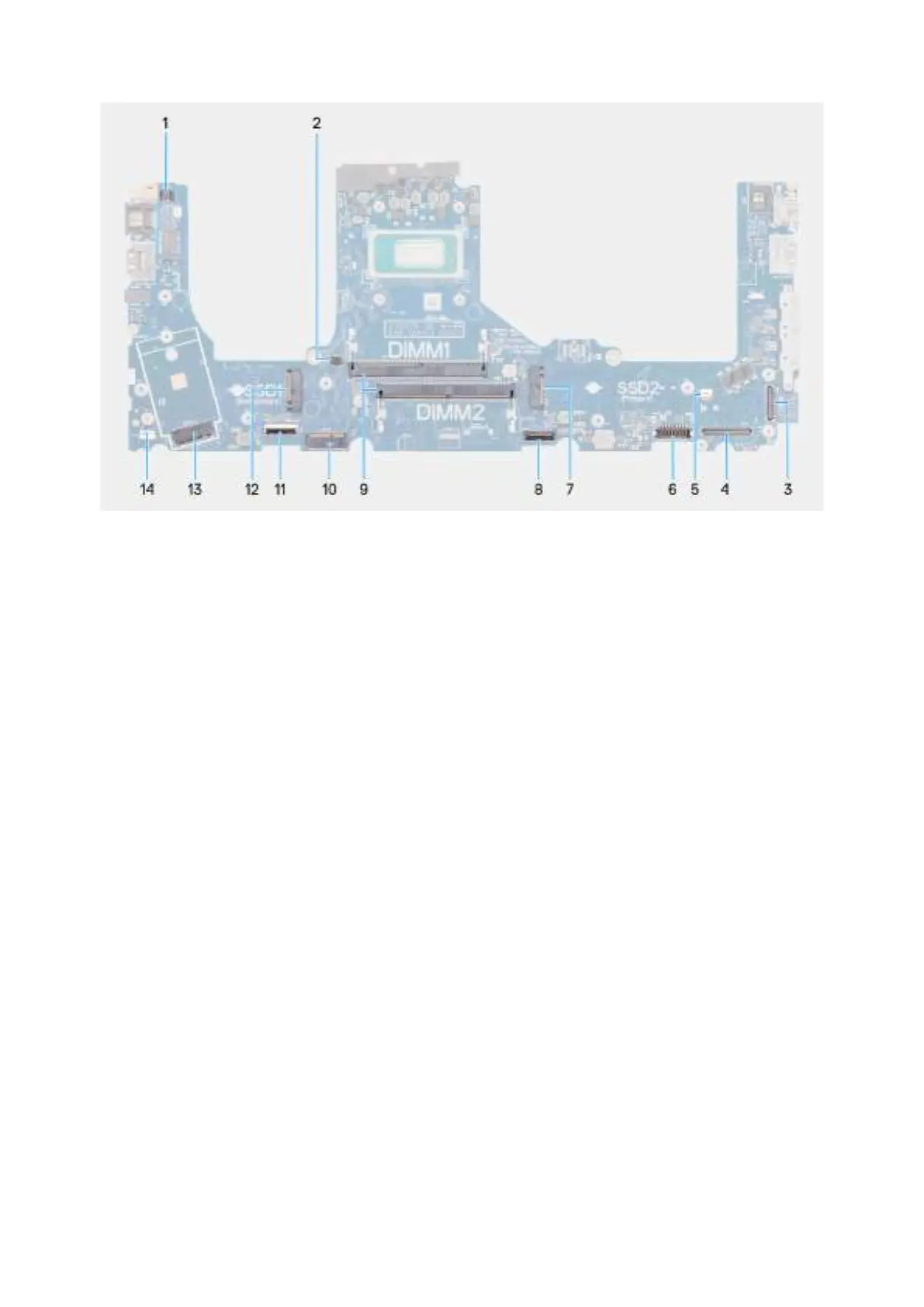
Figure 81. System board connectors
1. Fingerprint-reader cable connector (FP1)
2. Right/Processor-fan cable connector (FANL1)
3. IR-camera cable connector (CAM1)
4. Display-cable connector (LCD1)
5. Left/Video-fan cable connector (FANR2)
6. Battery-cable connector (BATT1)
7. Primary M.2 solid state drive connector (SSD2)
8. Touchpad-cable connector (TPAD1)
9. Memory-module connectors (DIMM1 and DIMM2)
10. Wireless-card connector (WLAN1)
11. USH-board cable connector (CN661)
12. Secondary M.2 solid state drive connector (SSD1)
13. WWAN-module connector (WWAN1)
14. Speaker-cable connector (SPK1)
The following images indicate the location of the system board and provide a visual representation of the installation procedure.
114
Removing and installing Field Replaceable Units (FRUs)