HYBRID Coater Service Manual ver1.1 Chapter 3
17
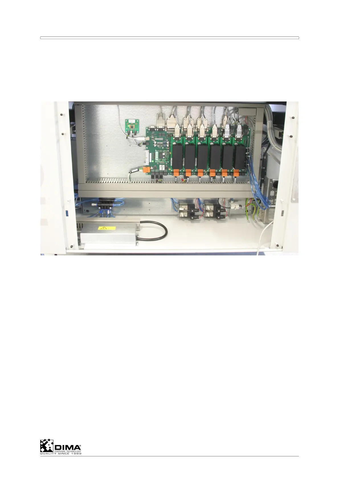
3.6 Electrical Compartment in Rear
This compartment contains:
Electro panel with EL-04873 Control PCB and EL-04872 Advanced Power LED Control
(See wiring diagrams HC-0200-0315 and HC-0200-0415).
Mounting bracket for external connections (Ethernet, USB etc.).
The EL-04873 Control PCB contains the complete control of the machine. It get its
commands from the Personal Computer. On this PCB two different types of PCB’s are
present:
One EL-04548 Processor Module. This module contains a very powerful processor and
fast memory. The embedded software can be flashed in this module. Updating the
program can be done by the machine.
Up to six EL-04874 Stepper Driver Modules. These modules are used to drive the stepper
motors of the machine. The position of a module determines for which function a stepper
is used. From left to right: X, Y, Z, Ø, Conveyor 1(front), Conveyor 2 (rear). If a function is
not used the corresponding position stays empty. Each module gets its own 48Volt power
supply. A LED is present on the bottom side of each module indicating the presence of
this 48Volt. On the module only the power part of the stepper control is located.
NOTE: The modules are identical, so interchangeable for testing purposes.
On the right side of the EL-04873 Control PCB up to 8 Pressure Sensors may be present.
Numbers are present on the PCB indicating the sensor number of the position. On
position 1 (bottom, right) is always a pressure sensor present. This one is used to
measure the pressure of the incoming air supply. The other ones are optional (for use in
combination with HC-1050 and HC1051 option). See appendix E for more information.