HYBRID Coater Service Manual ver1.1 Chapter 9
77
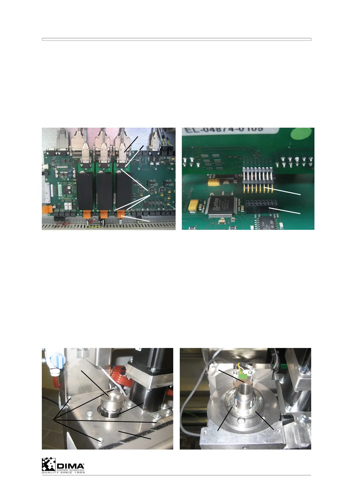
9.6 Replacing PCB’s of Stepper Motors
The PCB’s for the stepper motors are located in the rear of the bottom compartment of the
HYBRID on the large PCB. You can identify which PCB corresponds to which stepper motor
by the identification of the wires leading to the top of this PCB.
Disconnect the connectors (#1) and (#4) on top and on the bottom of the PCB (#2). Undo
the three cross-head screws (#3) on the PCB and replace the PCB. Pay Attention that the
leads (#5) at the under side of the PCB (#2) fit precisely in the socket (#6) of the large
PCB. Couple the connectors to the PCB.
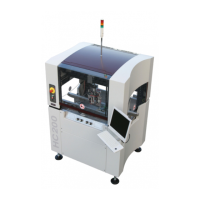
9.7 Replacing and Adjusting the Encoder
Only the HC-200 uses an encoder for accuracy. It is placed on top of the drive shaft motor for
this Ø axis.
NOTE: Place Tool 1 in front (Ctrl + 1) and try not to rotate the Ø axis during this procedure!
The line (#6) on the Encoder Disc (#7) has to be in the middle of the Encoder
Sensor (#6) after replacing it. This way this coating head always has the correct 0
(Zero) degrees position. The encoder disc consists of a metal ring on which a plastic
ring with an orientation line is bonded.
A Undo the sensor nut (#1) on top of the drive shaft (#2).
ATTENTION: Don’t use pliers; you can hold the rotation of the coating head underneath by
hand and the undo the sensor nut (#1) on top by hand.
6
5
1
3
2
4
5
6
7
1
4
2
3