Chapter 3 HYBRID Coater Service Manual ver1.1
10
C From there (#1) the main air pressure is distributed directly to an air switch #4 on the
coating head (with HC-100 = figure 3a). Or to the air switch #5 on the fixed part of the
coating head (with HC-200 = figure 3b).
3a 3b
3.3.2 Air Lines Routing of the Options
3.3.2.1 With Options HC-1050 or HC-1051
Kit HC-1051 is intended for pressure up to 2.5 bar for atomizing air. Kit HC-1050 is intended
for pressure up to 7 bar for a tank or cartridge. These kits contain one pressure reducing
valve, one solenoid valve with bracket, one pressure sensor, one Y connection and four air
lines and some fasteners.
A For this purpose an air line runs directly from the distribution block (#1) to the Pressure
Reducing Valve (#6) either No. 1050 or No. 1051. The outlet line from the Pressure
Reducing Valve goes into the cable duct above the bottom in the rear compartment of the
machine.
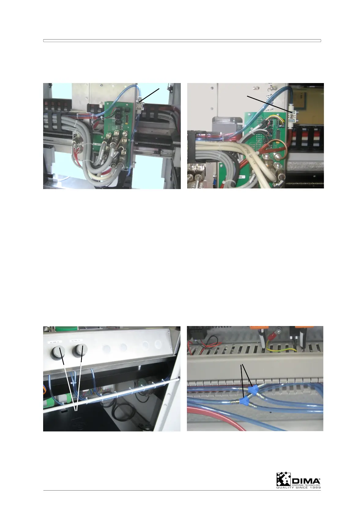
B Here it splits in an Y connection (#7). The long end runs to the pressure sensor (#8) on
the large PCB (the next free position).
4
5
6
7