Chapter 3 HYBRID Coater Service Manual ver1.1
12
E The previous figure shows an example of a HC-100 equipped with various tools. Here the
air lines are taken from the front of the coating head. They are controlled by the pressure
reducing valves from the front panel and the controlled pressure is put on the fluid in the
cartridge or syringe.
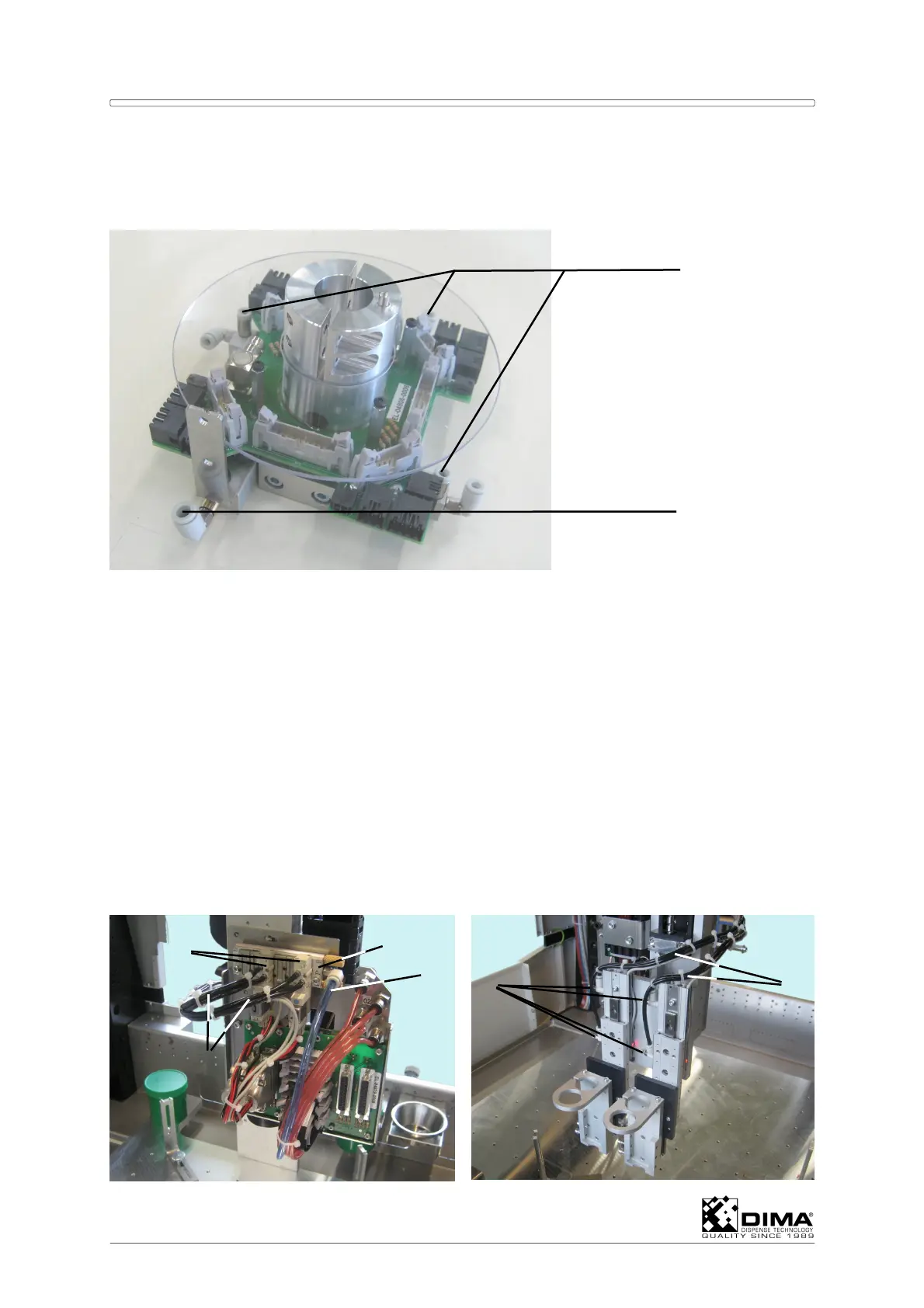
F At a HC-200 these air lines run in a flexible duct several times around the coating head
into the interconnections A1, B1, and C1 as seen in Block Diagram of Air at the beginning
of this chapter. The Y connection is the main air IN.
G However it is possible that the three connections on the coating head aren’t sufficient,
then it is possible to run the air line directly to one of the tanks (inside or outside the
working area). From there a fluid line can run to a tool on the coating head.
3.3.2.2 With Options HC-1000, HC-1010, or HC-1030
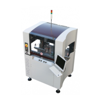
A At the HC-100 the air line is continued at the underside of the switch (#4) into the flexible
air duct. And from there to the inlet connection (#13) of the air block (#14). The air block
is used to distribute the pressure of the main air to the various solenoid valves #15 which
are mounted on it. From here two air lines #16 run down to each tool on the front of the
Coating Head. This way you can perform an OUT and IN function on a tool. Like a slide
function down and up (see example), or tilt function out and in! The speed regulation is
done on the tool with the small knobs (#17).
A1, B1, C1
#Y
13
15
14
16
16
17