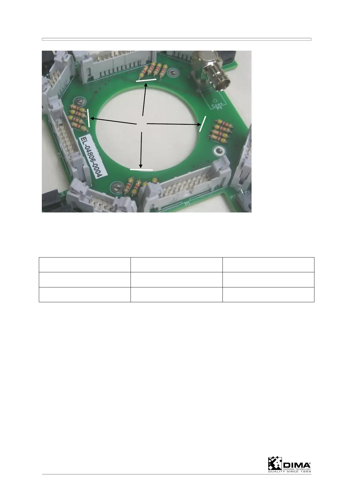
Chapter 4 HYBRID Coater Service Manual ver1.1
34
D The brown and blue wire have to be connected to the corresponding connector on the
right hand side of the unit. This means that the wires from Unit 1 are connected to the
next free places on connector P21. Then from Unit 2 to connector 22 and so on.
EXAMPLE: Connector to #P21 (this can also be P22, P23, or P24)
connector on #P21 Pin allocation Standard
Black wire (signal) 5, or 7 5
Brown wire (24V) 6, or 8 6
E The black wire (signal) assigns which sensor input (Sensor In) from Appendix I is used.
Here the standard #5 assigns it to StdSensorIn01. From this the Level Empty Detection
can be configured on the HybridC screen in Options/Configuration/ then I/O and Digital
Inputs under Ref. all the way down till reaching StdSensorIn01. Here the checkbox Inv
has to be marked. Now the PC can find the sensor. In the same window under
Dispensers the corresponding dispenser has to be opened. Then under Level
detection, the checkbox has to show LevelSensor.
F Open Options/Test Machine Parts, then I/O under Name, the corresponding level
sensor appears and can be tested there.
4.7 Installing Options HC-1380 and HC-1390
The preparation for valve heating HC-1380 and HC-1390 are of similar layout. The only
difference is that the HC-1380 is designed for the HC-100 and the HC-1390 is designed for
the HC-200.
For the HC-200 a different Flexible Cable Duct is needed, the HC-100-SS-51 has to be
exchanged for the HC-100-SS-55.
A